Weider 9000 Uk Manual - Page 14
Bench Assembly
 |
View all Weider 9000 manuals
Add to My Manuals
Save this manual to your list of manuals |
Page 14 highlights
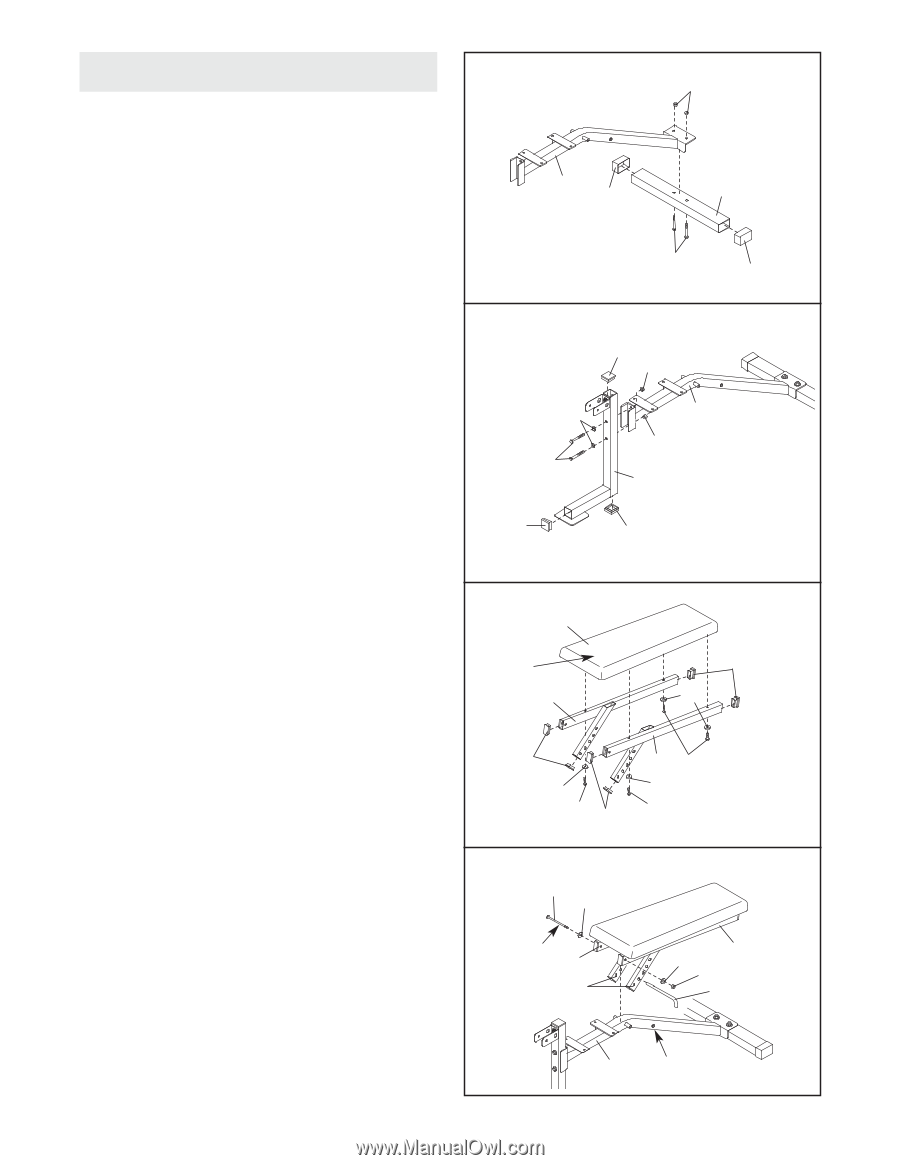
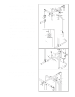
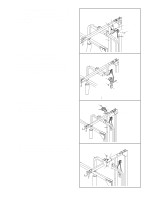
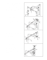
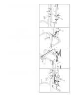
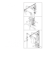
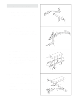
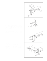
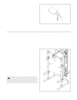
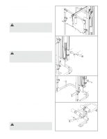
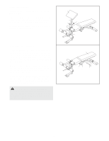
Bench Assembly 29 29. Press two 51mm x 76mm Outer Caps (79) onto the Stabiliser (62). Attach the Stabiliser to the Bench Frame (63) with two M10 x 60mm Carriage Bolts (50) and two M10 Nylon Locknuts (49). 63 79 49 62 30. Press three 50mm Square Inner Caps (43) into the Front Leg (64). Attach the Front Leg (64) to the Bench Frame (63) with two M10 x 65mm Bolts (54), two M10 Washers (52), and two M10 Nylon Locknuts (49). 50 79 30 43 49 52 54 63 49 64 43 43 31. Orient the Right and Left Backrest Frames (67, 68) as shown. Press six 25mm x 50mm Inner Caps (82) into the Backrest Frames. Orient the Bench Backrest (69) with the wide end on the side shown. Attach the Backrest to the Backrest Frames (67, 68) with four M6 x 63mm Bolts (56) and four M6 Washers (59). Do not tighten the Bolts yet. 32. Lubricate the M10 x 180mm Bolt (78) with grease. Attach the Backrest Frames (67, 68) to the Bench Frame (63) with the Bolt, two M10 Washers (52), and an M10 Nylon Locknut (49). Insert the Bench Pin (74) through a set of holes in the adjustment tubes on the Backrest Frames (67, 68) and the indicated hole in the Bench Frame (63). Tighten the M6 x 63mm Bolts (56) used in step 31. 31 69 Wide End 67 82 59 82 59 56 82 68 56 59 56 32 78 52 Lubricate 67 Adjustment Tubes 68 52 49 74 63 Hole 14
-
 1
1 -
2
-
3
-
4
-
5
-
6
-
7
-
8
-
 9
9 -
 10
10 -
 11
11 -
 12
12 -
 13
13 -
 14
14 -
 15
15 -
 16
16 -
 17
17 -
 18
18 -
 19
19 -
20
-
21
-
22
-
23
-
24
-
25
-
26
-
27
-
28
 |
 |