Whirlpool ECKMF94 Installation Guide
Whirlpool ECKMF94 - Automatic Ice Maker Manual
 |
UPC - 050946418711
View all Whirlpool ECKMF94 manuals
Add to My Manuals
Save this manual to your list of manuals |
Whirlpool ECKMF94 manual content summary:
- Whirlpool ECKMF94 | Installation Guide - Page 1
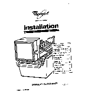
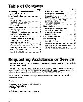
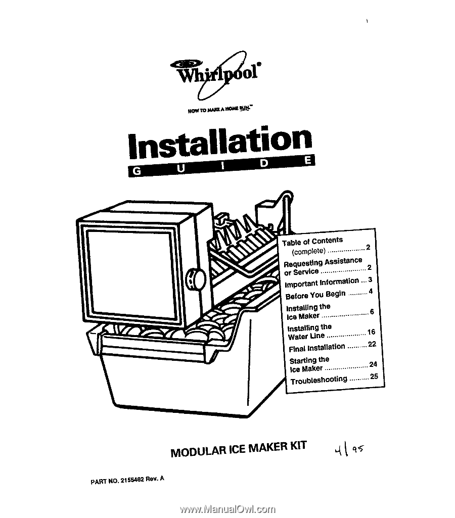
Requesting of Service Assistance 2 1 cmpoftant Inf of mation ...3 Before You Begin .......... 4 Installing the Ice Maker 6 1 Installing the I Water une 16 Final installation .,........ 22 Starting the ice Maker 24 TrOubleshOOting .......... 25 MODULAR ICEMAKER KIT PART NO. 2155462 - Whirlpool ECKMF94 | Installation Guide - Page 2
Final installation 22 Installing the access cover and forming the copper tubing 22 Connecting the power/ leveling the unit 23 Starting the ice Maker 24 Troubleshooting 25 Operational notes 25 Troubleshooting chart 25 The modular ice maker service sheet .... 26 Ice maker replacement parts list - Whirlpool ECKMF94 | Installation Guide - Page 3
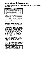
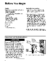
potentially dangerous conditions. These conditions can cause serious personal injury if the suggested procedures are not observed. @ThisInstallation Guide gives you complete instructions on how to install the Ice Maker Kit in your refrigerator-freezer and connect a water line to it. Please read the - Whirlpool ECKMF94 | Installation Guide - Page 4
a close-up illustration of a certain portion of a diagram or an illustration of a specific step you are to perform. DETAILS are labeled A, B, or C and are clearly referenced in each step. 3. When you are instructed to install a part, position the part as shown in the illustration. Important safety - Whirlpool ECKMF94 | Installation Guide - Page 5
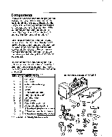
Fill tube Gasket Short extension tube Long extension tube* ice maker clips* Tubing clips Metal water tube insert Water valve tubing clamp % ' hex-head sheet-metal screws N'hex-head machine screws %' hex-head sheet-metal screws l For installation in Side-By-Side Models only. COMPONENT ILLUSTRATIONS - Whirlpool ECKMF94 | Installation Guide - Page 6
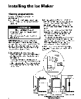
to access the areas to install the ice maker. 3.On an appliance with a bottom freezer, remove the slide-out basket, the ice cube trays, and the wire ice cube holder (if necessary, refer to your "Use and Care Guide" for the procedure). Set these items aside. On top-mount models without a full-width - Whirlpool ECKMF94 | Installation Guide - Page 7
tab into slot Break off and discard Ice maker wiring cover 000 Foam insert Removing the label and foam plug Refer to the side diagram for the following steps. 1. Locate the fill tube and the round foam gasket from the ice maker kit (the gasket may already be installed on the fill tube). If not - Whirlpool ECKMF94 | Installation Guide - Page 8
A). Some kits may have a long straight plastic extension in place of the long bent aluminum extension. Install the plastic Installing the long fill tube extension Refer back to the side diagram for the following step. 2. Position the wiring harness so that it is through the slot in the wiring - Whirlpool ECKMF94 | Installation Guide - Page 9
freezer models Refer to the side diagram for the following steps. 1. Remove the phillips screw from the ice maker wiring cover, unhook the right side tab from the edge of the back cover, and remove the wiring cover. Mounting hole - Phillips 2. Look at the back side of the wiring cover screw - Whirlpool ECKMF94 | Installation Guide - Page 10
Installing the tubing clips Refer to the side diagram for the following steps. 1. Remove the seven hex-head screws from the rear access cover, then remove Right channel / rDETAlL B 9 Tubing clio Top and SXS freezers Tubing CliD Bottom freexere 18xacces8 cover DETAlLA - Installing the tubing clips 10 - Whirlpool ECKMF94 | Installation Guide - Page 11
Preparing the water valve (for bottom freezers only) Refer to the side diagram for the following steps. tubing 1. Untape the coiled flexible tubing coming from the water valve and straighten it. 2. Starting at the top of the compression - Whirlpool ECKMF94 | Installation Guide - Page 12
Mounting the water valve Refer to the diagram below for the following steps. 1. Locate the 2-pin water valve solenoid connector (with the brown and two white wires) that is taped to the main wiring harness at the lower right corner of the rear access (see DETAIL A). 3. Refer to DETAIL B and mount - Whirlpool ECKMF94 | Installation Guide - Page 13
diagram below for the following steps. 1. Refer to the inset in DETAIL A and pull the plastic insert out of the fill tube spout and discard it. 2. Locate the water valve tubing clamp (from the ice maker kit into the two clips (see DETAIL C) you installed earlier on the back of the cabinet. You - Whirlpool ECKMF94 | Installation Guide - Page 14
tube will fit through this cutout when you install the ice maker. Remove knockout Removing the knockout Refer to the side diagram for the following /-' DETAlLA . steps. 1 SXS MODELS W hex-head 1. Remove and discard the blank connector from the wiring harness. To remove it, lift the locking - Whirlpool ECKMF94 | Installation Guide - Page 15
and connect its wiring connector to the wiring harness connector so they lock together (the locking arm will snap over the raised tab). The connectors will fit together only one way. 2. For Top/Bottom Freezers Only: Hang the ice maker over the two hex-head screws you installed earlier. Make sure - Whirlpool ECKMF94 | Installation Guide - Page 16
Installing the Water Line Choosing a location 1. Open the copper tubing kit that you purchased earlier, and lay the contents neatly on a table where you can identify them easily. The parts from the kit Hazard Make sure there are no electrical wires underneath the floor where the hole is to be - Whirlpool ECKMF94 | Installation Guide - Page 17
diagram for the following steps. 1. Uncoil the necessary length of copper tubing and straighten it, then route the end of the tubing through the access hole you drilled to the location you have chosen to install injury. Failure to follow these instructions could result in death or personal injury. - Whirlpool ECKMF94 | Installation Guide - Page 18
Installing the shut-off valve Refer to the diagram below for the following steps. 1. Locate the shut-off valve and the front pipe clamp (with the threaded hole in the center) from the copper tubing kit. Then, being careful not to crossthread the valve, screw the end with the pilot tube into the - Whirlpool ECKMF94 | Installation Guide - Page 19
Connecting the copper tubing Refer to the diagram below for the following steps. to the shut-off valve 1. it is approximately 1 'from the end. 4. Insert the end of the copper tubing into the outlet connector of the shut-off valve as far as it will go, and then hand tighten the compression nut as - Whirlpool ECKMF94 | Installation Guide - Page 20
to the diagram below open-end wrench, and further tighten the compression nut on the water inlet connector gne additional turq. If necessary, you will tighten the nut further after "from the end. Watec inlet fitting 8. If one is installed, remove the plastic cap from the water inlet fitting on the - Whirlpool ECKMF94 | Installation Guide - Page 21
and check the shut-off valve for leakage. If necessary, refer to the side diagram, and tighten the compression nut on the shut-off valveh sma I inc eme ts any leakage. If necessary, tighten the compression nut (see the side diagram) in small increments until the leak&g iust stops. T-handle / - Whirlpool ECKMF94 | Installation Guide - Page 22
near the center of the unit so that it forms an 'accordion-fold" (as shown in the diagram below) when it is moved toand-from the wall. Form tubing loops as I shown I - Copper tubing Place water valve tubing 7 behind cover I . Installing the access cover and forming the copper tubing 22 - Whirlpool ECKMF94 | Installation Guide - Page 23
to adjust the front casters, as outlined in your refrigerator's "Use and Care Guide." 3. Check the position of the ice maker. If it is -IT crooked and needs to be adjusted, loosen the bottom bracket screws (see the side diagram) and position the unit as desired, then tighten the bracket screws - Whirlpool ECKMF94 | Installation Guide - Page 24
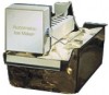
make two or three batches of ice and discard them. After that, the "off-taste" should be gone. If you have any problems, refer to 'Troubleshooting" on page 25. This completes the installation of your Ice Maker. 24 Installing the ice bucket Raise arm to * stop ice off Lower arm to Turning the - Whirlpool ECKMF94 | Installation Guide - Page 25
as a water source, you should consider installing a second water strainer in the water line. You can obtain a water strainer from your local appliance dealer. Troubleshooting chart The following chart lists several common problems that could occur with your Ice Maker. PROBLEM One or more of the - Whirlpool ECKMF94 | Installation Guide - Page 26
PLUG-IN CONNECTORS CYCLE - ONE REVOLUTION (EJECTS AND WATER FILL) FOR 120 VOLT MODEL MODULE VOLTAGE CHECKS WITH METER OR TEST LIGHT (POWER TO ICE MAKER) TEST I I LINE I 0 MODULE OHMMETER CHECKS (NO POWER TO ICE MAKER AND EJECTOR BLADES IN PARK) TEST 1 I MODULE I Service Procedures COVER - Whirlpool ECKMF94 | Installation Guide - Page 27
Screw, (3) 14 627792 Shut-off Arm 15 628256 Wiring, Harness 16 2155021 Clip, Ice Maker 17 489128 Screw, 8-32 x 27164" 18 1115846 Cover 19 628366 Module Assembly (Includes Items 10, 11, and 12) 20 627929 Valve, Solenoid 21 1115844 Knob, Water 22 628229 Bracket 23 628379 - Whirlpool ECKMF94 | Installation Guide - Page 28
Ice maker replacement parts The following parts are not illustrated. Optional parts are not included in this list. Part Service Cord Plastic Tube Nut and Sleeve Assembly Insert, Plastic Tube Accessory Bag, Inside Screw, 8 x l/2' Tube, Water Inlet Wiring Assembly, Ice Maker list (cont'd) PART
-
 1
1 -
 2
2 -
 3
3 -
 4
4 -
 5
5 -
 6
6 -
 7
7 -
8
-
9
-
10
-
11
-
12
-
13
-
14
-
15
-
16
-
17
-
18
-
19
-
20
-
21
-
22
-
23
-
24
-
25
-
26
-
27
-
28
 |
 |
Y
1
Table
of
Contents
(complete)
. . . . . . . . . . . . . . . . . . . 2
Requesting
Assistance
of
Service
..,,
...................
2
cmpoftant
Inf of
mation
...3
Before
You
Begin
. . . . . . . . . . 4
Installing
the
Ice Maker
.,
......
. . . . . . .. . . . . . . . . 6
1
I
Installing
the
Water une
..............
......
16
Final
installation
.,
........
22
Starting
the
ice Maker
......................
24
TrOubleshOOting
. . . . .. . . . .
25
MODULAR
ICE MAKER KIT
PART NO. 2155462 Rev.
A