Whirlpool ECKMF94 Installation Guide - Page 14
Mounting, ice maker - model
 |
UPC - 050946418711
View all Whirlpool ECKMF94 manuals
Add to My Manuals
Save this manual to your list of manuals |
Page 14 highlights
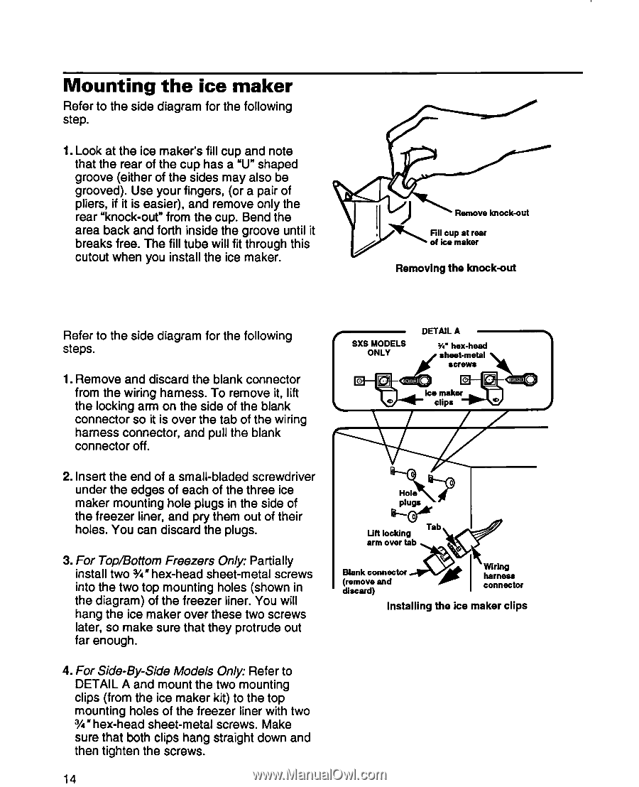
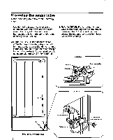
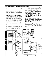
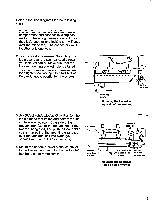
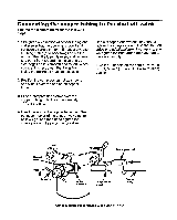
Mounting the ice maker Refer to the side diagram for the following step. 1. Look at the ice maker's fill cup and note that the rear of the cup has a "U" shaped groove (either of the sides may also be grooved). Use your fingers, (or a pair of pliers, if it is easier), and remove only the rear "knock-out" from the cup. Bend the area back and forth inside the groove until it breaks free. The fill tube will fit through this cutout when you install the ice maker. Remove knockout Removing the knockout Refer to the side diagram for the following /-' DETAlLA . steps. 1 SXS MODELS W hex-head 1. Remove and discard the blank connector from the wiring harness. To remove it, lift the locking arm on the side of the blank connector so it is over the tab of the wiring harness connector, and pull the blank connector off. 2. Insert the end of a small-bladed screwdriver under the edges of each of the three ice maker mounting hole plugs in the side of the freezer liner, and pry them out of their holes. You can discard the plugs. 3. For Top/Bottom Freezers Only: Partially install two %" hex-head sheet-metal screws into the two top mounting holes (shown in the diagram) of the freezer liner. You will hang the ice maker over these two screws later, so make sure that they protrude out far enough. PlYJet' 1 Lift locking arm over tab I Blank connector a (remove and discard) Installing Wring harness -1 connector the ice maker clips 4. For Side-By-Side Models Only: Refer to DETAIL A and mount the two mounting clips (from the ice maker kit) to the top mounting holes of the freezer liner with two S'hex-head sheet-metal screws. Make sure that both clips hang straight down and then tighten the screws. 14
-
 1
1 -
2
-
3
-
4
-
5
-
6
-
7
-
8
-
 9
9 -
 10
10 -
 11
11 -
 12
12 -
 13
13 -
 14
14 -
 15
15 -
 16
16 -
 17
17 -
 18
18 -
 19
19 -
20
-
21
-
22
-
23
-
24
-
25
-
26
-
27
-
28
 |
 |