Whirlpool ECKMF94 Installation Guide - Page 13
Connecting, the water, valve, tubing - ice maker kit
 |
UPC - 050946418711
View all Whirlpool ECKMF94 manuals
Add to My Manuals
Save this manual to your list of manuals |
Page 13 highlights
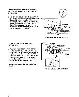
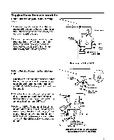
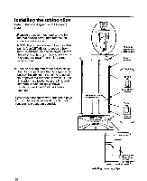
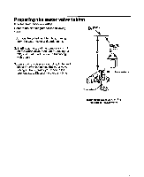
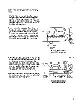
Connecting the water valve Refer to the diagram below for the following steps. 1. Refer to the inset in DETAIL A and pull the plastic insert out of the fill tube spout and discard it. 2. Locate the water valve tubing clamp (from the ice maker kit), and note that one of the flanges is made for a threaded screw and the other side has a round hole. Position this clamp with the round hole side facing up, and slide it over the end of the spout (see DETAILS A and 6). Thread a 55" hexhead sheet metal screw into the clamp with your fingers as far as possible. You will tighten the screw later. 3. Refer to DETAIL A, and position the metal water tube insert as shown, then press it all the way into the water valve tubing. tubing 4. Refer to DETAIL 6, and slide the end of the tubing into the end of the fill tube spout as far as it will go (if the tubing does not reach, pull as much as necessary up through the clips), then tighten the tubing clamp screw as much as possible. Pull on the tubing to make sure that it is secure. If it slides out of the spout, push it back in, and tighten the clamp screw further until the tubing is secure. 5. Press the tubing into the two clips (see DETAIL C) you installed earlier on the back of the cabinet. You will connect the free end of the tubing later. 6. Pull any excess tubing near the fill tube down throuah the two clamps so it forms a straight line-with a loop at the bottom of the water valve. II - P DETAlL B -.. . . Slide over clamp spout d + * Fill tub HF I= 'Tighten\ wrew on spout a8 much as possible Insert tubinf into spout a8 far a8 poesible I DETAIL A , *pout Water valve tublng clamp H' hex-head sheet-metal Connecting the water valve tubing to the fill tube
-
 1
1 -
2
-
3
-
4
-
5
-
6
-
7
-
 8
8 -
 9
9 -
 10
10 -
 11
11 -
 12
12 -
 13
13 -
 14
14 -
 15
15 -
 16
16 -
 17
17 -
 18
18 -
19
-
20
-
21
-
22
-
23
-
24
-
25
-
26
-
27
-
28
 |
 |
