Yamaha CDR-HD1300 Owner's Manual - Page 18
Connections
 |
View all Yamaha CDR-HD1300 manuals
Add to My Manuals
Save this manual to your list of manuals |
Page 18 highlights
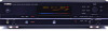
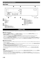
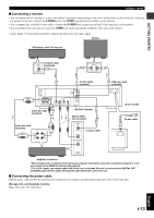
NAMES OF BUTTONS AND CONTROLS Rear Panel 1 2 3 L L R R 4 REC PLAY 3 LINE IN - LINE OUT ANALOG VIDEO OUT S VIDEO VIDEO COAXIAL OPTICAL COAXIAL OPTICAL IN OUT DIGITAL RS-232C 4 5 1 HDD slot 2 VIDEO OUT jacks S VIDEO jack VIDEO jack 3 AC inlet 4 ANALOG jacks ANALOG LINE IN (REC) jacks ANALOG LINE OUT (PLAY) jacks 6 (U.S.A. model) 5 DIGITAL jacks DIGITAL IN (COAXIAL) jack DIGITAL IN (OPTICAL) jack DIGITAL OUT (COAXIAL) jack DIGITAL OUT (OPTICAL) jack 6 RS-232C terminal CONNECTIONS Turn off the power of this unit and the other components, and unplug them from the wall outlet before making any connections. I Digital connections • This unit has the DIGITAL OPTICAL jacks and DIGITAL COAXIAL jacks. Connect either the DIGITAL OPTICAL jacks, or the DIGITAL COAXIAL jacks according to the component to be connected. • Using the optical fiber cable, connect the DIGITAL IN (OPTICAL) jack on this unit to the digital optical output jack on the other component, and the DIGITAL OUT (OPTICAL) jack on this unit to the digital optical input jack on the other component. • When using the DIGITAL IN/OUT (COAXIAL) jacks, make connections with coaxial cables. Connect the DIGITAL IN (COAXIAL) jack on this unit to the digital coaxial output jack on the other component, and the DIGITAL OUT (COAXIAL) jack on this unit to the digital coaxial input jack on the other component. I Analog connections • Make sure to connect the L (left) and R (right) input and output jacks on this unit to the correct L (left) and R (right) input and output jacks on the other component. • Connect the ANALOG LINE IN (REC) jack on this unit to the analog output jack on the other component, and the ANALOG LINE OUT (PLAY) jack on this unit to the analog input jack on the other component. • The ANALOG LINE IN (REC)/LINE OUT (PLAY) jacks on this unit are numbered # and $ respectively. Connect these jacks to the jacks with the same numbers when connecting this unit to a Yamaha amplifier or receiver. • To connect the turntable directly to this unit, first connect it to the phono equalizer and then connect to the ANALOG LINE IN (REC) jacks on this unit. Notes • When you play the data on the HDD or CDs, signals are output both from the ANALOG LINE OUT (PLAY) jack and from the DIGITAL OUT (OPTICAL/COAXIAL) jacks. • Signals that are output through the DIGITAL OUT (OPTICAL) jacks or the DIGITAL OUT (COAXIAL) jacks while playing the data on the HDD do not have information about the track markers. Therefore if these signals are recorded by an MD player, the track markers may not be placed correctly on the recorded MD disc. E-12
-
 1
1 -
2
-
3
-
4
-
5
-
6
-
7
-
8
-
9
-
10
-
11
-
12
-
 13
13 -
 14
14 -
 15
15 -
 16
16 -
 17
17 -
 18
18 -
 19
19 -
 20
20 -
 21
21 -
 22
22 -
 23
23 -
24
-
25
-
26
-
27
-
28
-
29
-
30
-
31
-
32
-
33
-
34
-
35
-
36
-
37
-
38
-
39
-
40
-
41
-
42
-
43
-
44
-
45
-
46
-
47
-
48
-
49
-
50
-
51
-
52
-
53
-
54
-
55
-
56
-
57
-
58
-
59
-
60
-
61
-
62
-
63
-
64
-
65
-
66
-
67
-
68
-
69
-
70
-
71
-
72
-
73
-
74
-
75
-
76
-
77
-
78
-
79
-
80
-
81
-
82
-
83
-
84
-
85
-
86
-
87
-
88
-
89
-
90
-
91
-
92
-
93
-
94
-
95
-
96
-
97
-
98
-
99
-
100
-
101
-
102
-
103
-
104
-
105
-
106
 |
 |
