Yamaha CS1x Owner's Manual - Page 30
ASSIGN2, Press the DATA Parameter Value UP/DOWN button
 |
View all Yamaha CS1x manuals
Add to My Manuals
Save this manual to your list of manuals |
Page 30 highlights
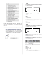
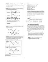
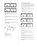
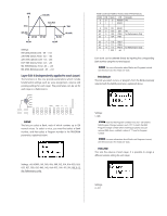
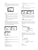
s ASSIGN2 This sets the control parameter and knob sensitivity of the ASSIGN 2 Sound Control Knob. It is possible to assign up to four parameters from 28 types. It is also possible to set the sensitivity (control range of the knob) for each parameter. The parameter assigned to the ASSIGN2 knob as the default differs depending on the Performance selected. 1. Select the Layer. Press the LAYER [-]/[+] button to select the Layer to which you want to assign a parameter. 2. Select the item (parameter type or sensitivity) you want to edit and the assignment number which you want to assign the parameter to. Press the Parameter Value [UP] button to select the item (parameter type or sensitivity) you want to edit, and the assignment number. Each time you press the (PARAM) Parameter Value [UP] button, the arrow cursor will move as shown in the following illustration. Parameter Type Layer Sensitivity Assignment Number Parameter type of assignment number 1 Sensitivity of assignment number 1 Parameter type of assignment number 2 Sensitivity of assignment number 2 Parameter type of assignment number 3 Sensitivity of assignment number 3 Parameter type of assignment number 4 Sensitivity of assignment number 4 vw Each time you press the (PARAM) Parameter [DOWN] button, the arrow cursor will move in the opposite direction. 3. Move the cursor to the Parameter type area and press the (DATA) Parameter UP/DOWN button to select the parameter type. Settings: The following parameters can be assigned to assignment number 1 ~ 4. For details about each parameter, see the reference pages as listed below. NOTE When voices are not assigned to the Layers (Bank=Off), Parameter type and sensitivity will not display. # LCD 0 off 1 Volume (page 33) 2 NoteShift (page 27) 3 Detune (page 27) 4 Pan (page 34) 5 ChorusSend (page 38) 6 ReverbSend (page 38) 7 *Pitch (Oscillator Pitch) 8 VelSnsDpth (Velocity Sensitivity Depth) (page 28) 9 VelSnsOfst (Velocity Sensitivity Offset) (page 28) 10 Cutoff (Filter Cuttoff Frequency) (page 34) 11 Resonance (page 34) 12 AEGAtkTime (AEG Attack Time) (page 30) 13 AEGDcyTime (AEG Decay Time) (page 30) 14 AEGSusLvl (AEG Sustain Level) (page 30) 15 AEGRelTime (AEG Release Time) (page 30) 16 LFOSpeed (LFO Speed) (page 31) 17 LFOAMod (LFO Amplitude Modulation Depth) (page 30) 18 LFOPMod (LFO Pitch Modulation Depth) (page 30) 19 LFOFMod (LFO Filter Modulation Depth) (page 31) 20 FEGAtkTime (FEG Attack Time) (page 32) 21 FEGDcyTime (FEG Decay Time) (page 32) 22 FEGSusLvl (FEG Sustain Level) (page 32) 23 FEGRelTime (FEG Release Time) (page 32) 24 PEGInitLvl (PEG Initial Level) (page 32) 25 PEGAtkTime (PEG Attack Time) (page 32) 26 PEGAtkLvl (PEG Attack Level) (page 32) 27 PEGDcyTime (PEG Decay Time) (page 32) 28 PEGRelTime (PEG Release Time) (page 32) 29 PEGRelLvl (PEG Release Level) (page 32) Parameter with an asterisk cannot be modified, but you can assign it to the ASSIGN2 knob. Each parameter can also be selected by inputting the number with the numeric keypad. 4. Press the (PARAM) Parameter Value UP/DOWN button to move the arrow cursor to the sensitivity area. 5. Press the (DATA) Parameter Value UP/DOWN button to set the knob sensitivity. Settings: Parameters can be set between -32 and +32, for assignment numbers 1 ~ 4. NOTE As an example, say you have selected the Volume parameter and set the knob sensitivity to the positive value "+32". The volume is "0" when the knob is turned counter-clockwise to the far left, and "127" when the knob is turned clockwise to the far right. If the knob sensitivity is set to the negative value "-32", the volume is "127" when the knob is turned to the far left and "0" when the knob is turned to the far right. If the sensitivity value is small, the control range of the knob will be narrowed and limited. 6. Repeat the above steps to set a different parameter/knob sensitivity value to each of the four assignment numbers. NOTE When the PARAM screen is displayed, you can select the parameter type or change the sensivity using the Data Entry knob or the numeric keypad. 29
-
 1
1 -
2
-
3
-
4
-
5
-
6
-
7
-
8
-
9
-
10
-
11
-
12
-
13
-
14
-
15
-
16
-
17
-
18
-
19
-
20
-
21
-
22
-
23
-
24
-
 25
25 -
 26
26 -
 27
27 -
 28
28 -
 29
29 -
 30
30 -
 31
31 -
 32
32 -
 33
33 -
 34
34 -
 35
35 -
36
-
37
-
38
-
39
-
40
-
41
-
42
-
43
-
44
-
45
-
46
-
47
-
48
-
49
-
50
-
51
-
52
-
53
-
54
-
55
-
56
-
57
-
58
-
59
-
60
-
61
-
62
-
63
-
64
 |
 |
