Yamaha RX-V496 Owner's Manual - Page 13
CONNECTIONS, Before Connecting Components
 |
View all Yamaha RX-V496 manuals
Add to My Manuals
Save this manual to your list of manuals |
Page 13 highlights
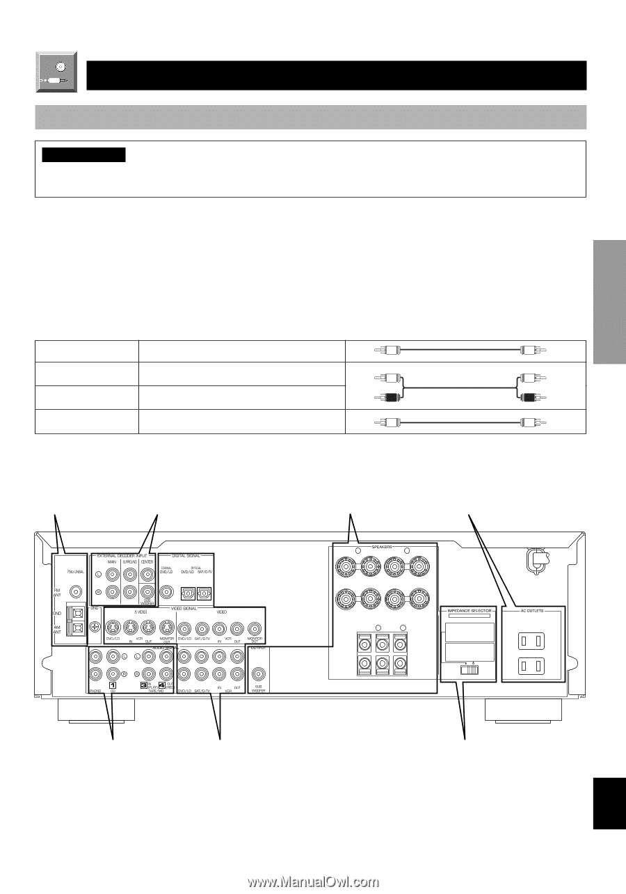
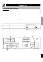
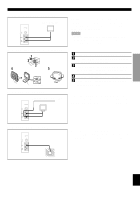
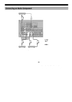
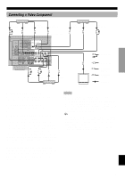
INTRODUCTION PREPARATION BASIC OPERATION ADVANCED OPERATION CONNECTIONS Before Connecting Components CAUTION Never connect this unit and other components to mains power until all connections between components have been completed. Be sure all connections are made correctly, that is to say L (left) to L, R (right) to R, "+" to "+" and "-" to "-". Some components require different connection methods and have different terminal names. Refer to the instructions for each component to be connected to this unit. When you connect other YAMAHA audio components (such as a tape deck, MD recorder and CD player or changer), connect it to the terminals with the same number labels as !, #, $ etc. YAMAHA applies this labeling system to all its products. Use RCA-type pin plug cables for connecting audio/video components with the exception described later. The input and output terminals for pin plugs can be distinguished as follows: Yellow video signals (composite) V V White analog audio signals for the left channel L L Red analog audio signals for the right channel R R coaxial digital signals C C After completing all connections, check them again to make sure they are correct. Connecting the Connecting to an External Antenna (page 10) Decoder (page 14) Connecting Speakers (page 15) Connecting the Power Supply Cords (page 17) (U.S.A. model) + R - MAIN - L + A MAINS CENTER R REAR (SURROUND) L + + - - B SET BEFORE POWER ON MAIN A OR B : 4ΩMIN. /SPEAKER A + B : 8ΩMIN. /SPEAKER CENTER : 6ΩMIN. /SPEAKER REAR : 6ΩMIN. /SPEAKER MAIN A OR B : 8ΩMIN. /SPEAKER A + B : I6ΩMIN. /SPEAKER CENTER : 8ΩMIN. /SPEAKER REAR : 8ΩMIN. /SPEAKER 120 V 60Hz 100W MAX. TOTAL SWITCHED Connecting an Audio Component (page 12) Connecting a Video Component (page 13) IMPEDANCE SELECTOR switch (page 17) APPENDIX English 9
-
 1
1 -
2
-
3
-
4
-
5
-
6
-
7
-
 8
8 -
 9
9 -
 10
10 -
 11
11 -
 12
12 -
 13
13 -
 14
14 -
 15
15 -
 16
16 -
 17
17 -
 18
18 -
19
-
20
-
21
-
22
-
23
-
24
-
25
-
26
-
27
-
28
-
29
-
30
-
31
-
32
-
33
-
34
-
35
-
36
-
37
-
38
-
39
-
40
-
41
-
42
-
43
-
44
-
45
-
46
-
47
-
48
-
49
-
50
-
51
-
52
-
53
-
54
-
55
-
56
-
57
-
58
-
59
-
60
-
61
-
62
-
63
 |
 |