Yamaha RX-V496 Owner's Manual - Page 17
Connecting a Video Component, Audio signal terminals
 |
View all Yamaha RX-V496 manuals
Add to My Manuals
Save this manual to your list of manuals |
Page 17 highlights
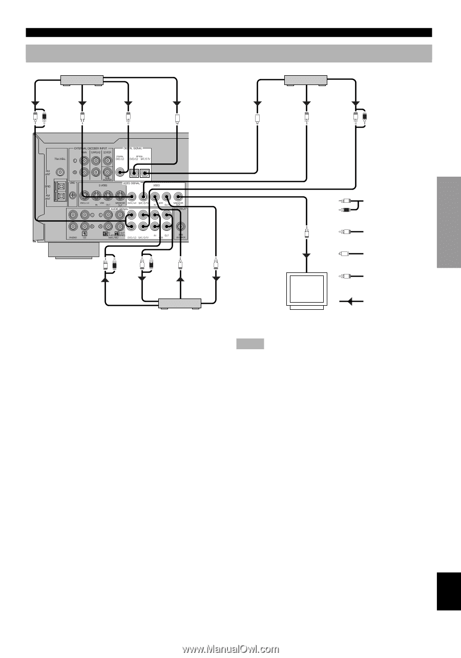
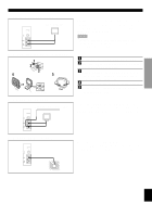
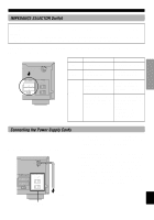
Connecting a Video Component DVD/LD player ANALOG AUDIO OUT VIDEO OUT LR V COAXIAL DIGITAL OUT OPTICAL DIGITAL OUT C O (U.S.A. model) CONNECTIONS TV/digital TV, satellite tuner, cable TV OPTICAL DIGITAL OUT VIDEO OUT O V ANALOG AUDIO OUT LR INTRODUCTION PREPARATION BASIC OPERATION ADVANCED OPERATION L Analog signal R LR LR AUDIO OUT AUDIO IN V V VIDEO OUT VIDEO IN VCR V V O VIDEO IN C TV monitor Video signal Digital signal (optical) Digital signal (coaxial) Signal flow s Audio signal terminals Be sure to connect the right channel (R), left channel (L), input (IN) and output (OUT) properly. s Video signal terminals Be sure to connect the input (IN) and output (OUT) properly. s Digital audio signal terminals If your DVD/LD player, TV/digital TV or satellite tuner, etc. has coaxial or optical digital signal output terminals, they can be connected to this unit's COAXIAL and/or OPTICAL digital signal input terminals. To make a connection between the optical digital signal terminals, remove the cover from each terminal, and then connect them by using a commercially available optical fiber cable that conforms to EIA standards. Other cables might not function correctly. When making connections between the digital signal terminals, you should connect the components to the samenamed analog audio signal terminals of this unit, because a digital signal cannot be recorded by a tape deck, MD recorder or VCR connected to this unit. Notes • Be sure to attach the covers when the OPTICAL terminals are not being used in order to protect them from dust. • If your LD player has a Dolby Digital RF signal output terminal, be sure to use the RF demodulator (separately purchased). • No sound will be heard when connecting your LD player's Dolby Digital RF signal output terminal directly to this unit's COAXIAL DVD/LD digital signal input terminal. y • The input signal from the DVD/LD input terminals is selected in the following order of priority with the input mode set to AUTO: COAXIAL terminal → OPTICAL terminal → Analog terminal. Refer to page 22 for details. • All digital signal input terminals are applicable to sampling frequencies of 32 kHz, 44.1 kHz and 48 kHz. 13 APPENDIX English
-
 1
1 -
2
-
3
-
4
-
5
-
6
-
7
-
8
-
9
-
10
-
11
-
 12
12 -
 13
13 -
 14
14 -
 15
15 -
 16
16 -
 17
17 -
 18
18 -
 19
19 -
 20
20 -
 21
21 -
 22
22 -
23
-
24
-
25
-
26
-
27
-
28
-
29
-
30
-
31
-
32
-
33
-
34
-
35
-
36
-
37
-
38
-
39
-
40
-
41
-
42
-
43
-
44
-
45
-
46
-
47
-
48
-
49
-
50
-
51
-
52
-
53
-
54
-
55
-
56
-
57
-
58
-
59
-
60
-
61
-
62
-
63
 |
 |