Yamaha RX-V496 Owner's Manual - Page 21
IMPEDANCE SELECTOR Switch, Connecting the Power Supply Cords, AC OUTLETS SWITCHED
 |
View all Yamaha RX-V496 manuals
Add to My Manuals
Save this manual to your list of manuals |
Page 21 highlights
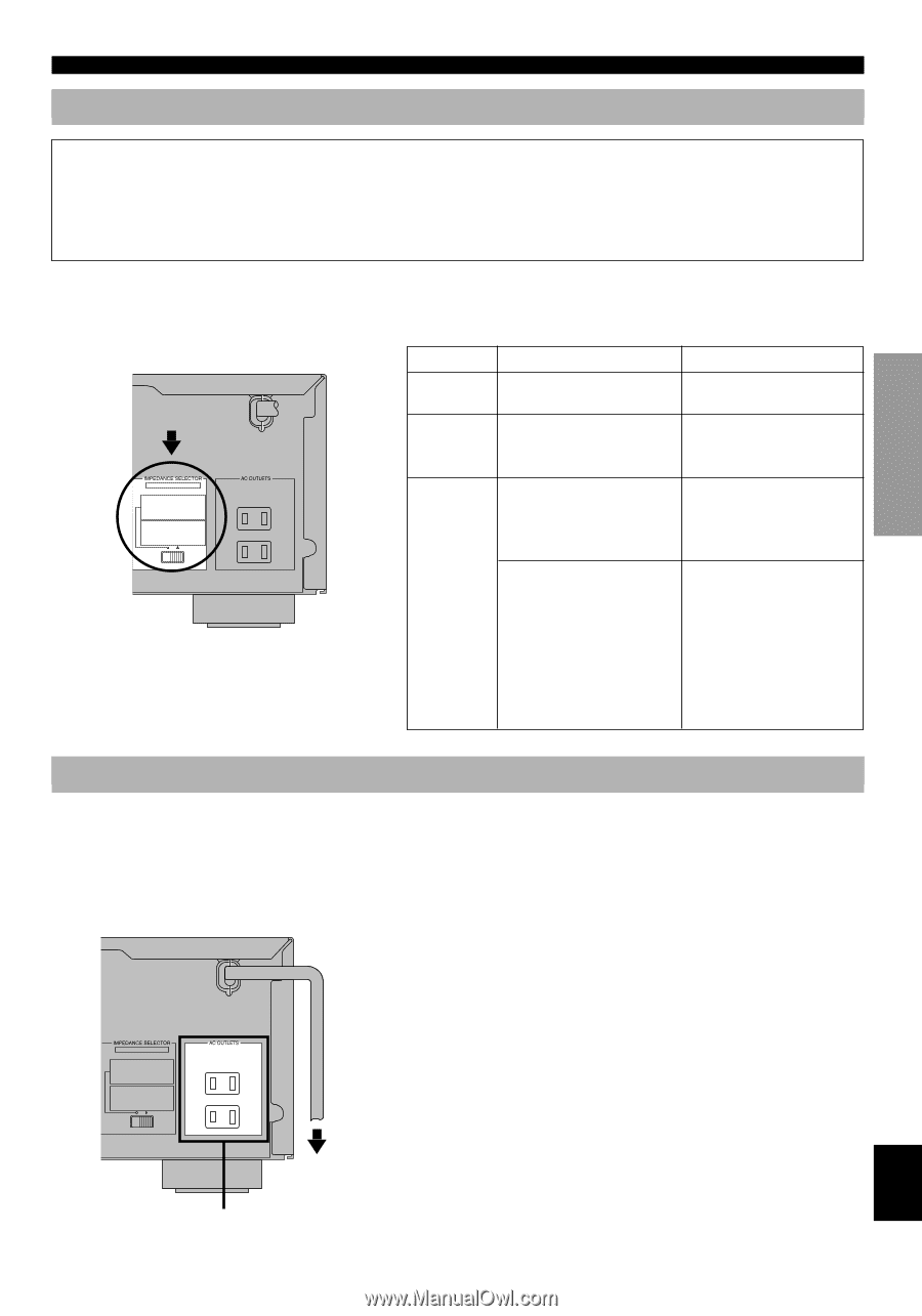
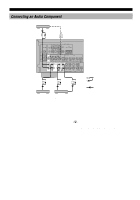
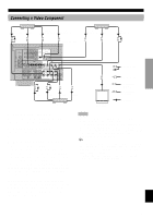
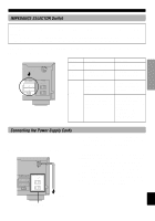
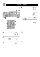
INTRODUCTION PREPARATION BASIC OPERATION ADVANCED OPERATION CONNECTIONS IMPEDANCE SELECTOR Switch WARNING Do not change the IMPEDANCE SELECTOR switch setting while the power to this unit is on, otherwise the unit may be damaged. If this unit fails to turn on when STANDBY/ON is pressed, the IMPEDANCE SELECTOR switch may not be fully slide to either position. If so, slide the switch to either position fully when this unit is in the standby mode. Select the right or left position according to the impedance of speakers in your system. Be sure to move this switch only when this unit is in the standby mode. (U.S.A. model) IMPEDANCE MAINS SELECTOR SET BEFORE POWER ON MAIN A OR B : 4ΩMIN. /SPEAKER A + B : 8ΩMIN. /SPEAKER CENTER : 6ΩMIN. /SPEAKER REAR : 6ΩMIN. /SPEAKER MAIN A OR B : 8ΩMIN. /SPEAKER A + B : I6ΩMIN. /SPEAKER CENTER : 8ΩMIN. /SPEAKER REAR : 8ΩMIN. /SPEAKER 120 V 60Hz 100W MAX. TOTAL SWITCHED If you use Center speaker Rear speakers Main speakers left position The impedance must be 6 Ω or higher. The impedance of each speaker must be 6 Ω or higher. If you use one pair of main speakers, the impedance of each speaker must be 4 Ω or higher. If you use two pairs of main speakers, the impedance of each speaker must be 8 Ω or higher. right position The impedance must be 8 Ω or higher. The impedance of each speaker must be 8 Ω or higher. If you use one pair of main speakers, the impedance of each speaker must be 8 Ω or higher. If you use two pairs of main speakers, the impedance of each speaker must be 16 Ω or higher. [Canada model only] The impedance of each speaker must be 8 Ω or higher. Connecting the Power Supply Cords s AC OUTLETS (SWITCHED) (U.S.A. model) MAINS SET BEFORE POWER ON MAIN A OR B : 4ΩMIN. /SPEAKER A + B : 8ΩMIN. /SPEAKER CENTER : 6ΩMIN. /SPEAKER REAR : 6ΩMIN. /SPEAKER MAIN A OR B : 8ΩMIN. /SPEAKER A + B : I6ΩMIN. /SPEAKER CENTER : 8ΩMIN. /SPEAKER REAR : 8ΩMIN. /SPEAKER 120 V 60Hz 100W MAX. TOTAL SWITCHED After completing all connections, connect the AC power cord to an AC power outlet. Disconnect the AC power cord if you will not use this unit for a long period of time. U.S.A. and Canada models 2 OUTLETS Australia model 1 OUTLET Use these outlets to connect the power cords from your components to this unit. The power to the AC OUTLET(S) is controlled by this unit's STANDBY/ON (or POWER). These outlets will supply power to any connected component whenever this unit is turned on. The maximum power (total power consumption of components) that can be connected to the AC OUTLET(S) is 100 W. To AC outlet SWITCHED APPENDIX English 17
-
 1
1 -
2
-
3
-
4
-
5
-
6
-
7
-
8
-
9
-
10
-
11
-
12
-
13
-
14
-
15
-
 16
16 -
 17
17 -
 18
18 -
 19
19 -
 20
20 -
 21
21 -
 22
22 -
 23
23 -
 24
24 -
 25
25 -
 26
26 -
27
-
28
-
29
-
30
-
31
-
32
-
33
-
34
-
35
-
36
-
37
-
38
-
39
-
40
-
41
-
42
-
43
-
44
-
45
-
46
-
47
-
48
-
49
-
50
-
51
-
52
-
53
-
54
-
55
-
56
-
57
-
58
-
59
-
60
-
61
-
62
-
63
 |
 |