ZyXEL ES-3124PWR User Guide - Page 116
Multiple Spanning Tree Protocol Status
 |
View all ZyXEL ES-3124PWR manuals
Add to My Manuals
Save this manual to your list of manuals |
Page 116 highlights
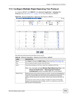
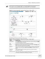
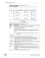
Chapter 11 Spanning Tree Protocol Table 31 Advanced Application > Spanning Tree Protocol > MSTP (continued) LABEL DESCRIPTION VLAN Range Enter the start of the VLAN ID range that you want to add or remove from the VLAN range edit area in the Start field. Enter the end of the VLAN ID range that you want to add or remove from the VLAN range edit area in the End field. Next click: • Add - to add this range of VLAN(s) to be mapped to the MST instance. • Remove - to remove this range of VLAN(s) from being mapped to the MST instance. • Clear - to remove all VLAN(s) from being mapped to this MST instance. Enabled VLAN(s) This field displays which VLAN(s) are mapped to this MST instance. Port This field displays the port number. * Settings in this row apply to all ports. Use this row only if you want to make some settings the same for all ports. Use this row first to set the common settings and then make adjustments on a port-by-port basis. Active Priority Path Cost Add Cancel Instance VLAN Active Port Delete Cancel Note: Changes in this row are copied to all the ports as soon as you make them. Select this check box to add this port to the MST instance. Configure the priority for each port here. Priority decides which port should be disabled when more than one port forms a loop in the Switch. Ports with a higher priority numeric value are disabled first. The allowed range is between 0 and 255 and the default value is 128. Path cost is the cost of transmitting a frame on to a LAN through that port. It is recommended to assign this value according to the speed of the bridge. The slower the media, the higher the cost - see Table 24 on page 102 for more information. Click Add to save this MST instance to the Switch's run-time memory. The Switch loses this change if it is turned off or loses power, so use the Save link on the top navigation panel to save your changes to the non-volatile memory when you are done configuring. Click Cancel to begin configuring this screen afresh. This field displays the ID of an MST instance. This field displays the VID (or VID ranges) to which the MST instance is mapped. This field display the ports configured to participate in the MST instance. Check the rule(s) that you want to remove in the Delete column and then click the Delete button. Click Cancel to begin configuring this screen afresh. 11.9 Multiple Spanning Tree Protocol Status Click Advanced Application > Spanning Tree Protocol in the navigation panel to display the status screen as shown next. See Section 11.1.5 on page 104 for more information on MSTP. 116 ES-3124 Series User's Guide
-
 1
1 -
2
-
3
-
4
-
5
-
6
-
7
-
8
-
9
-
10
-
11
-
12
-
13
-
14
-
15
-
16
-
17
-
18
-
19
-
20
-
21
-
22
-
23
-
24
-
25
-
26
-
27
-
28
-
29
-
30
-
31
-
32
-
33
-
34
-
35
-
36
-
37
-
38
-
39
-
40
-
41
-
42
-
43
-
44
-
45
-
46
-
47
-
48
-
49
-
50
-
51
-
52
-
53
-
54
-
55
-
56
-
57
-
58
-
59
-
60
-
61
-
62
-
63
-
64
-
65
-
66
-
67
-
68
-
69
-
70
-
71
-
72
-
73
-
74
-
75
-
76
-
77
-
78
-
79
-
80
-
81
-
82
-
83
-
84
-
85
-
86
-
87
-
88
-
89
-
90
-
91
-
92
-
93
-
94
-
95
-
96
-
97
-
98
-
99
-
100
-
101
-
102
-
103
-
104
-
105
-
106
-
107
-
108
-
109
-
110
-
 111
111 -
 112
112 -
 113
113 -
 114
114 -
 115
115 -
 116
116 -
 117
117 -
 118
118 -
 119
119 -
 120
120 -
 121
121 -
122
-
123
-
124
-
125
-
126
-
127
-
128
-
129
-
130
-
131
-
132
-
133
-
134
-
135
-
136
-
137
-
138
-
139
-
140
-
141
-
142
-
143
-
144
-
145
-
146
-
147
-
148
-
149
-
150
-
151
-
152
-
153
-
154
-
155
-
156
-
157
-
158
-
159
-
160
-
161
-
162
-
163
-
164
-
165
-
166
-
167
-
168
-
169
-
170
-
171
-
172
-
173
-
174
-
175
-
176
-
177
-
178
-
179
-
180
-
181
-
182
-
183
-
184
-
185
-
186
-
187
-
188
-
189
-
190
-
191
-
192
-
193
-
194
-
195
-
196
-
197
-
198
-
199
-
200
-
201
-
202
-
203
-
204
-
205
-
206
-
207
-
208
-
209
-
210
-
211
-
212
-
213
-
214
-
215
-
216
-
217
-
218
-
219
-
220
-
221
-
222
-
223
-
224
-
225
-
226
-
227
-
228
-
229
-
230
-
231
-
232
-
233
-
234
-
235
-
236
-
237
-
238
-
239
-
240
-
241
-
242
-
243
-
244
-
245
-
246
-
247
-
248
-
249
-
250
-
251
-
252
-
253
-
254
-
255
-
256
-
257
-
258
-
259
-
260
-
261
-
262
-
263
-
264
-
265
-
266
-
267
-
268
-
269
-
270
-
271
-
272
-
273
-
274
-
275
-
276
-
277
-
278
-
279
-
280
-
281
-
282
-
283
-
284
-
285
-
286
-
287
-
288
-
289
-
290
-
291
-
292
-
293
-
294
-
295
-
296
-
297
-
298
-
299
-
300
-
301
-
302
-
303
-
304
-
305
-
306
-
307
-
308
-
309
-
310
-
311
-
312
-
313
-
314
-
315
-
316
-
317
-
318
-
319
-
320
-
321
-
322
-
323
-
324
-
325
-
326
-
327
-
328
-
329
-
330
-
331
-
332
-
333
-
334
-
335
-
336
-
337
-
338
-
339
-
340
-
341
-
342
-
343
-
344
-
345
-
346
-
347
-
348
-
349
-
350
-
351
-
352
-
353
-
354
 |
 |
