ZyXEL ES-3124PWR User Guide - Page 172
General MVR Configuration
 |
View all ZyXEL ES-3124PWR manuals
Add to My Manuals
Save this manual to your list of manuals |
Page 172 highlights
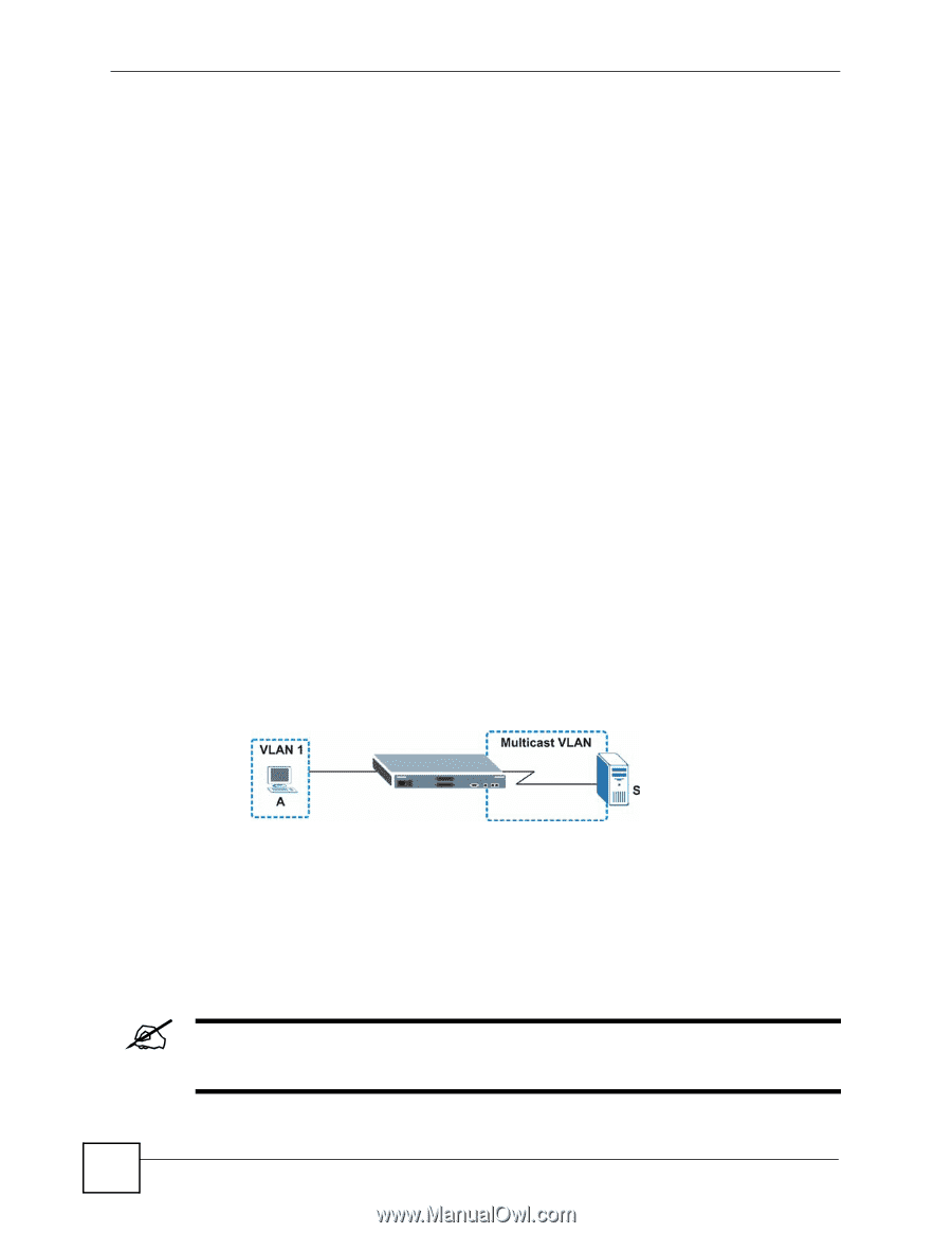
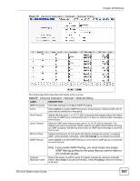
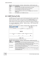
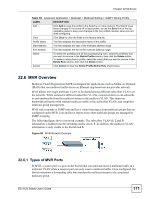
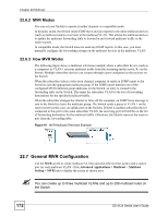
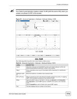
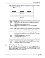
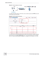
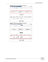
Chapter 22 Multicast 22.6.2 MVR Modes You can set your Switch to operate in either dynamic or compatible mode. In dynamic mode, the Switch sends IGMP leave and join reports to the other multicast devices (such as multicast routers or servers) in the multicast VLAN. This allows the multicast devices to update the multicast forwarding table to forward or not forward multicast traffic to the receiver ports. In compatible mode, the Switch does not send any IGMP reports. In this case, you must manually configure the forwarding settings on the multicast devices in the multicast VLAN. 22.6.3 How MVR Works The following figure shows a multicast television example where a subscriber device (such as a computer) in VLAN 1 receives multicast traffic from the streaming media server, S, via the Switch. Multiple subscriber devices can connect through a port configured as the receiver on the Switch. When the subscriber selects a television channel, computer A sends an IGMP report to the Switch to join the appropriate multicast group. If the IGMP report matches one of the configured MVR multicast group addresses on the Switch, an entry is created in the forwarding table on the Switch. This maps the subscriber VLAN to the list of forwarding destinations for the specified multicast traffic. When the subscriber changes the channel or turns off the computer, an IGMP leave message is sent to the Switch to leave the multicast group. The Switch sends a query to VLAN 1 on the receiver port (in this case, an uplink port on the Switch). If there is another subscriber device connected to this port in the same subscriber VLAN, the receiving port will still be on the list of forwarding destination for the multicast traffic. Otherwise, the Switch removes the receiver port from the forwarding table. Figure 91 MVR Multicast Television Example 22.7 General MVR Configuration Use the MVR screen to create multicast VLANs and select the receiver port(s) and a source port for each multicast VLAN. Click Advanced Applications > Multicast > Multicast Setting > MVR link to display the screen as shown next. " You can create up to three multicast VLANs and up to 256 multicast rules on the Switch. 172 ES-3124 Series User's Guide
-
 1
1 -
2
-
3
-
4
-
5
-
6
-
7
-
8
-
9
-
10
-
11
-
12
-
13
-
14
-
15
-
16
-
17
-
18
-
19
-
20
-
21
-
22
-
23
-
24
-
25
-
26
-
27
-
28
-
29
-
30
-
31
-
32
-
33
-
34
-
35
-
36
-
37
-
38
-
39
-
40
-
41
-
42
-
43
-
44
-
45
-
46
-
47
-
48
-
49
-
50
-
51
-
52
-
53
-
54
-
55
-
56
-
57
-
58
-
59
-
60
-
61
-
62
-
63
-
64
-
65
-
66
-
67
-
68
-
69
-
70
-
71
-
72
-
73
-
74
-
75
-
76
-
77
-
78
-
79
-
80
-
81
-
82
-
83
-
84
-
85
-
86
-
87
-
88
-
89
-
90
-
91
-
92
-
93
-
94
-
95
-
96
-
97
-
98
-
99
-
100
-
101
-
102
-
103
-
104
-
105
-
106
-
107
-
108
-
109
-
110
-
111
-
112
-
113
-
114
-
115
-
116
-
117
-
118
-
119
-
120
-
121
-
122
-
123
-
124
-
125
-
126
-
127
-
128
-
129
-
130
-
131
-
132
-
133
-
134
-
135
-
136
-
137
-
138
-
139
-
140
-
141
-
142
-
143
-
144
-
145
-
146
-
147
-
148
-
149
-
150
-
151
-
152
-
153
-
154
-
155
-
156
-
157
-
158
-
159
-
160
-
161
-
162
-
163
-
164
-
165
-
166
-
 167
167 -
 168
168 -
 169
169 -
 170
170 -
 171
171 -
 172
172 -
 173
173 -
 174
174 -
 175
175 -
 176
176 -
 177
177 -
178
-
179
-
180
-
181
-
182
-
183
-
184
-
185
-
186
-
187
-
188
-
189
-
190
-
191
-
192
-
193
-
194
-
195
-
196
-
197
-
198
-
199
-
200
-
201
-
202
-
203
-
204
-
205
-
206
-
207
-
208
-
209
-
210
-
211
-
212
-
213
-
214
-
215
-
216
-
217
-
218
-
219
-
220
-
221
-
222
-
223
-
224
-
225
-
226
-
227
-
228
-
229
-
230
-
231
-
232
-
233
-
234
-
235
-
236
-
237
-
238
-
239
-
240
-
241
-
242
-
243
-
244
-
245
-
246
-
247
-
248
-
249
-
250
-
251
-
252
-
253
-
254
-
255
-
256
-
257
-
258
-
259
-
260
-
261
-
262
-
263
-
264
-
265
-
266
-
267
-
268
-
269
-
270
-
271
-
272
-
273
-
274
-
275
-
276
-
277
-
278
-
279
-
280
-
281
-
282
-
283
-
284
-
285
-
286
-
287
-
288
-
289
-
290
-
291
-
292
-
293
-
294
-
295
-
296
-
297
-
298
-
299
-
300
-
301
-
302
-
303
-
304
-
305
-
306
-
307
-
308
-
309
-
310
-
311
-
312
-
313
-
314
-
315
-
316
-
317
-
318
-
319
-
320
-
321
-
322
-
323
-
324
-
325
-
326
-
327
-
328
-
329
-
330
-
331
-
332
-
333
-
334
-
335
-
336
-
337
-
338
-
339
-
340
-
341
-
342
-
343
-
344
-
345
-
346
-
347
-
348
-
349
-
350
-
351
-
352
-
353
-
354
 |
 |