ZyXEL ES-3124PWR User Guide - Page 174
MVR Group Configuration
 |
View all ZyXEL ES-3124PWR manuals
Add to My Manuals
Save this manual to your list of manuals |
Page 174 highlights
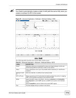
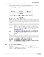
Chapter 22 Multicast Table 60 Advanced Application > Multicast > Multicast Setting > MVR (continued) LABEL DESCRIPTION * Settings in this row apply to all ports. Use this row only if you want to make some settings the same for all ports. Use this row first to set the common settings and then make adjustments on a port-by-port basis. Source Port Receiver Port None Tagging Add Cancel VLAN Active Name Mode Source Port Receiver Port 802.1p Delete Cancel Note: Changes in this row are copied to all the ports as soon as you make them. Select this option to set this port as the MVR source port that sends and receives multicast traffic. All source ports must belong to a single multicast VLAN. Select this option to set this port as a receiver port that only receives multicast traffic. Select this option to set the port not to participate in MVR. No MVR multicast traffic is sent or received on this port. Select this checkbox if you want the port to tag the VLAN ID in all outgoing frames transmitted. Click Add to save your changes to the Switch's run-time memory. The Switch loses these changes if it is turned off or loses power, so use the Save link on the top navigation panel to save your changes to the non-volatile memory when you are done configuring. Click Cancel to begin configuring this screen afresh. This field displays the multicast VLAN ID. This field displays whether the multicast group is enabled or not. This field displays the descriptive name for this setting. This field displays the MVR mode. This field displays the source port number(s). This field displays the receiver port number(s). This field displays the priority level. To delete a multicast VLAN(s), select the rule(s) that you want to remove in the Delete column, then click the Delete button. Click Cancel to clear the Delete check boxes. 22.8 MVR Group Configuration All source ports and receiver ports belonging to a multicast group can receive multicast data sent to this multicast group. Configure MVR IP multicast group address(es) in the Group Configuration screen. Click Group Configuration in the MVR screen. " A port can belong to more than one multicast VLAN. However, IP multicast group addresses in different multicast VLANs cannot overlap. 174 ES-3124 Series User's Guide
-
 1
1 -
2
-
3
-
4
-
5
-
6
-
7
-
8
-
9
-
10
-
11
-
12
-
13
-
14
-
15
-
16
-
17
-
18
-
19
-
20
-
21
-
22
-
23
-
24
-
25
-
26
-
27
-
28
-
29
-
30
-
31
-
32
-
33
-
34
-
35
-
36
-
37
-
38
-
39
-
40
-
41
-
42
-
43
-
44
-
45
-
46
-
47
-
48
-
49
-
50
-
51
-
52
-
53
-
54
-
55
-
56
-
57
-
58
-
59
-
60
-
61
-
62
-
63
-
64
-
65
-
66
-
67
-
68
-
69
-
70
-
71
-
72
-
73
-
74
-
75
-
76
-
77
-
78
-
79
-
80
-
81
-
82
-
83
-
84
-
85
-
86
-
87
-
88
-
89
-
90
-
91
-
92
-
93
-
94
-
95
-
96
-
97
-
98
-
99
-
100
-
101
-
102
-
103
-
104
-
105
-
106
-
107
-
108
-
109
-
110
-
111
-
112
-
113
-
114
-
115
-
116
-
117
-
118
-
119
-
120
-
121
-
122
-
123
-
124
-
125
-
126
-
127
-
128
-
129
-
130
-
131
-
132
-
133
-
134
-
135
-
136
-
137
-
138
-
139
-
140
-
141
-
142
-
143
-
144
-
145
-
146
-
147
-
148
-
149
-
150
-
151
-
152
-
153
-
154
-
155
-
156
-
157
-
158
-
159
-
160
-
161
-
162
-
163
-
164
-
165
-
166
-
167
-
168
-
 169
169 -
 170
170 -
 171
171 -
 172
172 -
 173
173 -
 174
174 -
 175
175 -
 176
176 -
 177
177 -
 178
178 -
 179
179 -
180
-
181
-
182
-
183
-
184
-
185
-
186
-
187
-
188
-
189
-
190
-
191
-
192
-
193
-
194
-
195
-
196
-
197
-
198
-
199
-
200
-
201
-
202
-
203
-
204
-
205
-
206
-
207
-
208
-
209
-
210
-
211
-
212
-
213
-
214
-
215
-
216
-
217
-
218
-
219
-
220
-
221
-
222
-
223
-
224
-
225
-
226
-
227
-
228
-
229
-
230
-
231
-
232
-
233
-
234
-
235
-
236
-
237
-
238
-
239
-
240
-
241
-
242
-
243
-
244
-
245
-
246
-
247
-
248
-
249
-
250
-
251
-
252
-
253
-
254
-
255
-
256
-
257
-
258
-
259
-
260
-
261
-
262
-
263
-
264
-
265
-
266
-
267
-
268
-
269
-
270
-
271
-
272
-
273
-
274
-
275
-
276
-
277
-
278
-
279
-
280
-
281
-
282
-
283
-
284
-
285
-
286
-
287
-
288
-
289
-
290
-
291
-
292
-
293
-
294
-
295
-
296
-
297
-
298
-
299
-
300
-
301
-
302
-
303
-
304
-
305
-
306
-
307
-
308
-
309
-
310
-
311
-
312
-
313
-
314
-
315
-
316
-
317
-
318
-
319
-
320
-
321
-
322
-
323
-
324
-
325
-
326
-
327
-
328
-
329
-
330
-
331
-
332
-
333
-
334
-
335
-
336
-
337
-
338
-
339
-
340
-
341
-
342
-
343
-
344
-
345
-
346
-
347
-
348
-
349
-
350
-
351
-
352
-
353
-
354
 |
 |