3Com 3CBLUG16A User Guide - Page 17
Connecting a Network Device, CAUTION
 |
UPC - 662705544489
View all 3Com 3CBLUG16A manuals
Add to My Manuals
Save this manual to your list of manuals |
Page 17 highlights
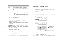
Color Yellow Off State Power-on self-test or loopback test failed. The Switch is in fail-safe mode. This can happen if a ports or ports fail when the Switch was powered on. The unit is not receiving power: ■ Verify that the power cord is connected correctly, and then try powering on the Switch again ■ If the Switch still does not operate, contact your 3Com network supplier If POST fails, try the following: ■ Power off the Switch, and then power it on again. Check the Power LED and see if POST was successfully completed. ■ Reset the Switch. See "Resetting to Factory Defaults" on page 43. CAUTION: Resetting the Switch to its factory defaults erases all your settings. You will need to reconfigure the Switch after you reset it. If these do not resolve the issue: ■ Check the 3Com Knowledgebase for a solution. To visit the 3Com Knowledgebase Web site, start your Web browser, and then enter http://knowledgebase.3com.com. ■ Contact your 3Com network supplier for assistance. Connecting a Network Device 17 Connecting a Network Device To connect a network device to the Switch, use Category 5 unshielded or shielded (screened) 100 Ohm TP cables (or Category 3 cables for 10 Mbps connections). For optimal connections, ensure that the cable length for each connection is not longer than 100 m (328 ft). Figure 3 Connecting Devices to the Switch Baseline 10/100 Switch Endstations on switched 100 Mbps connections Baseline 10/100 Switch Endstations on switched 100 Mbps connections BaselineBSawsietclihne28S1w6i/t2ch82242-5S0FP Plus 1000 Mbps copper or F iber connection to backbone or server/worksation 1000 Mbps link 10 Mbps or 100 Mbps link Endstations on switched 100 Mbps or 1000 Mbps connections To connect a device to the Switch: 1 Connect one end of the cable to an RJ-45 port on the Switch.
-
 1
1 -
2
-
3
-
4
-
5
-
6
-
7
-
8
-
9
-
10
-
11
-
 12
12 -
 13
13 -
 14
14 -
 15
15 -
 16
16 -
 17
17 -
 18
18 -
 19
19 -
 20
20 -
 21
21 -
 22
22 -
23
-
24
-
25
-
26
-
27
-
28
-
29
-
30
-
31
-
32
-
33
-
34
-
35
-
36
-
37
-
38
-
39
-
40
-
41
-
42
-
43
-
44
-
45
-
46
-
47
-
48
-
49
-
50
-
51
-
52
-
53
-
54
-
55
-
56
-
57
-
58
-
59
-
60
-
61
-
62
-
63
-
64
-
65
-
66
-
67
-
68
-
69
-
70
-
71
-
72
 |
 |
