3Com 3CBLUG16A User Guide - Page 37
Removing a VLAN, Configuring Link Aggregation
 |
UPC - 662705544489
View all 3Com 3CBLUG16A manuals
Add to My Manuals
Save this manual to your list of manuals |
Page 37 highlights
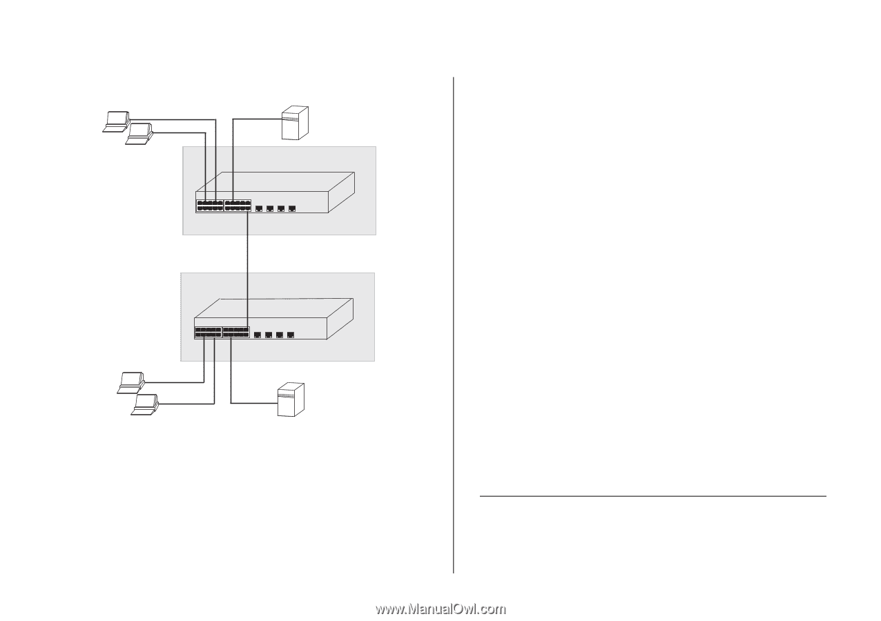
Figure 17 Uplink VLAN Configuration Endstation in VLAN 1 (Desktop) Server in VLAN 1 (Desktop) Endstation in VLAN 2 (Desktop) Switch 1 Switch 2 Port 16 in VLANs 1 and 2 (Uplink) Port 8 in VLANs 1 and 2 (Uplink) Endstation in VLAN 2 (Desktop) Server in VLAN 2 (Desktop) Endstation in VLAN 1 (Desktop) To set up the configuration shown in Figure 17, do the following: 1 Create VLAN2 on both Switch 1 and Switch 2, and assign the same name to it. You need not create VLAN1 since it exists by default. Configuring Link Aggregation 37 2 On Switch 1, set the ports that you want to be part of VLAN2 to D (desktop egress packet). Set one port (for example, port 16) to U (uplink egress packet). Click Apply. 3 On Switch 2, set the ports that you want to be part of VLAN2 to D (desktop egress packet). Set one port (for example, port 8) to U (uplink egress packet). Click Apply. 4 Connect the uplink port on Switch 1 (in this example, port 16) to the uplink port on Switch 2 (in this example, port 8). Those ports on Switch 1 that are members of VLAN2 can now communicate with those ports on Switch 2 that are members of VLAN2. Removing a VLAN To remove an existing VLAN: 1 In the VLAN ID list, select the VLAN ID that you want to delete. 2 Click Remove. The VLANs page refreshes, and the VLAN ID that you deleted disappears from the VLAN ID list. Configuring Link Aggregation Ports can be statically grouped into an aggregated link, also known as a "trunk". This increases the bandwidth of a network connection and ensures fault recovery.
-
 1
1 -
2
-
3
-
4
-
5
-
6
-
7
-
8
-
9
-
10
-
11
-
12
-
13
-
14
-
15
-
16
-
17
-
18
-
19
-
20
-
21
-
22
-
23
-
24
-
25
-
26
-
27
-
28
-
29
-
30
-
31
-
 32
32 -
 33
33 -
 34
34 -
 35
35 -
 36
36 -
 37
37 -
 38
38 -
 39
39 -
 40
40 -
 41
41 -
 42
42 -
43
-
44
-
45
-
46
-
47
-
48
-
49
-
50
-
51
-
52
-
53
-
54
-
55
-
56
-
57
-
58
-
59
-
60
-
61
-
62
-
63
-
64
-
65
-
66
-
67
-
68
-
69
-
70
-
71
-
72
 |
 |