Airlink AML001 Manual
Airlink AML001 Manual
 |
View all Airlink AML001 manuals
Add to My Manuals
Save this manual to your list of manuals |
Airlink AML001 manual content summary:
- Airlink AML001 | Manual - Page 1
PCI Modem Card User's Manual - Airlink AML001 | Manual - Page 2
Copyright 2002 All rights reserved. No part of this publication may be reproduced in any form by any means without the prior written permission. Other trademarks or brand names mentioned herein are trademarks or registered trademarks of their respective companies. April 2002, Rev01 - Airlink AML001 | Manual - Page 3
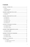
For Windows 2000/XP 20 CHAPTER 5 VERIFY MODEM INSTALLATION 21 5.1 For Windows 95/98/Me 21 5.2 For Windows 2000/XP 23 CHAPTER 6 UNINSTALLING THE DRIVERS 25 6.1 For Windows 98/Me 25 6.2 For Windows NT4.0 26 6.3 For Windows 2000/XP 27 APPENDIX A AT COMMANDS 29 A.1 AT Commands 29 A.1.1 Data - Airlink AML001 | Manual - Page 4
PCI Modem Card User's Manual A.2 Result Codes 64 A.3 S-Registers ...66 APPENDIX B SPECIFICATIONS 69 APPENDIX C GLOSSARY 75 APPENDIX D ASCII CODE TABLE 79 II - Airlink AML001 | Manual - Page 5
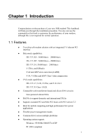
silicon DAA ! Bit I/Os to support domestic and international DAAs ! Supports standard PCI and Mini PCI buses with PCI version 2.2 ! Ideal for mobile computing and high performance/low power applications ! Flexible power management modes ! Common driver across multiple platforms ! Operating system - Airlink AML001 | Manual - Page 6
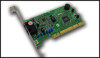
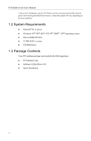
PCI Modem Card User's Manual * Due to FCC limitations, speeds of 53 kbits/s are the maximum permissible transmit power levels during download -ROM drive 1.3 Package Contents Your PCI modem package must include the following items: ! PCI Modem Card ! Software Utility/Driver CD ! Quick Installation 2 - Airlink AML001 | Manual - Page 7
modem card. After hardware installation, turn on your computer and the system should detect the modem upon startup. Proceed to next section to install the drivers. 3 - Airlink AML001 | Manual - Page 8
Installation 3.1 For Windows 95 Start Windows 95 and insert the provided CD into your CD-ROM drive to start driver installation. Step 1 The Update Device Driver Wizard screen will appear detecting a new device and request for the driver. Click Next. Step 2 Windows will be unable to locate the - Airlink AML001 | Manual - Page 9
Manual Step 3 Click Browse to specify the path to X:\Driver\Win9x where X is the CD-ROM drive letter and click OK. Step 4 Step 5 Step 6 Step 7 Windows will find the location of the driver to specify the path to X:\Driver\Win9x where X is the CD you are done with driver installation, you will need - Airlink AML001 | Manual - Page 10
Wizard screen will appear detecting a new device and request for the driver. Click Next. Step 2 Select Search for the best driver for you device and click Next. Step 3 Check Specify a location, click Browse to specify the path to X:\Driver\Win9x where X is your CD-ROM drive letter and click OK - Airlink AML001 | Manual - Page 11
PCI Modem Card User's Manual Step 4 Windows will find the location of the driver; click Next. Step 5 Click Finish. Step 6 Windows will continue to detect the voice device. Click Next and then repeat steps 2-5 to complete the installation. When you are done with driver installation, you will need to - Airlink AML001 | Manual - Page 12
Next. Step 2 Insert the provided CD into your CD-ROM drive. Select Search for the best driver for your device and then check only the Specify a location box. Click Browse to specify the path to X:\Driver\WinME where X is your CD-ROM drive letter and click Next. Step 3 When Windows finds the - Airlink AML001 | Manual - Page 13
telecommunication regulations/ laws. Please proceed to "Chapter 4 Configuring Countries" on page 17 for instructions. 3.4 For Windows NT4.0 Step 1 Click Start menu and then click Run. Click Browse to open the file Setup.exe from X:\Driver\NT40 where X is your CD-ROM drive letter and click OK. 10 - Airlink AML001 | Manual - Page 14
Step 2 When confirm message appears, click OK. Step 3 When prompted to restart your computer, click OK. When you are done with driver installation, you will need to specify the country where you locate upon different telecommunication regulations/laws. Please proceed to "Chapter 4 Configuring - Airlink AML001 | Manual - Page 15
PCI Modem Card User's Manual 3.5 For Windows 2000 Start Windows 2000 and insert the provided CD into your CD-ROM drive to start driver installation. Step 1 The Found New Hardware Wizard screen will appear detecting a new device and request for the driver. Click Next. Step 2 Select Search for a - Airlink AML001 | Manual - Page 16
and click OK. Step 5 Step 6 Windows will find the location of the driver; click Next. If Digital Signature Not Found window appears, click Yes to continue. for Windows to complete the installation. When you are done with driver installation, you will need to specify the country where you locate - Airlink AML001 | Manual - Page 17
PCI Modem Card User's Manual 3.6 For Windows XP Start Windows XP and insert the provided CD into your CD-ROM drive to start driver installation. Step 1 When Found New Hardware Wizard screen appears, select Install from a list or specific location (Advanced) and click Next. Step 2 With Search for - Airlink AML001 | Manual - Page 18
3 Software Installation Step 4 Click Finish. When Found New Hardware screen appears, wait for completing the installation. When you are done with driver installation, you will need to specify the country where you locate upon different telecommunication regulations/ laws. Please proceed to "Chapter - Airlink AML001 | Manual - Page 19
Chapter 4 Configuring Countries Before using the modem, you may need to specify the country where you locate upon different telecommunication regulations/ laws. If you have configured your country during the installation process, just ignore this section. 4.1 For Windows 95/98/Me Note: If you are - Airlink AML001 | Manual - Page 20
PCI Modem Card User's Manual Step 3 From the drop-down list of I am in (for Windows 95) or I am in this country/region (for Windows 98/Me), select a country where - Airlink AML001 | Manual - Page 21
Chapter 4 Configuring Countries Step 2 In Modems Properties window, highlight Agere Systems PCI Soft Modem and click Dialing Properties. Step 3 From the drop-down list of I am in this country/region, select a country where your modem is to be used and click Apply and then OK. 19 - Airlink AML001 | Manual - Page 22
PCI Modem Card User's Manual 4.3 For Windows 2000/XP Note: The configuration steps are the same in Windows 2000 and Windows XP. The graphics here assume a Windows 2000 environment. Step 1 - Airlink AML001 | Manual - Page 23
Chapter 5 Verify Modem Installation If you are going to install data/fax communications software, you may start with a quick test to check that the Windows can communicate with your modem. 5.1 For Windows 95/98/Me Step 1 Step 2 Click Start menu, point to Settings and then click Control Panel. - Airlink AML001 | Manual - Page 24
PCI Modem Card User's Manual Step 3 Highlight the COM port used by your modem and then click AT...) should appear on the screen. Congratulations! You have successfully installed the modem hardware and its driver. * According to your model, the command responses may differ from shown above. Note: If - Airlink AML001 | Manual - Page 25
Chapter 5 Verify Modem Installation 5.2 For Windows 2000/XP Note: The verification steps are the same in Windows 2000 and Windows XP. The graphics here assume a Windows 2000 environment. Step 1 Step 2 Click Start menu, point to Settings and then click Control Panel. Double-click the Phone and - Airlink AML001 | Manual - Page 26
PCI Modem Card User's Manual Step 4 Step 5 Wait for communication with your modem. If your modem is properly installed, the command response (something like AT...) should appear on the screen. Congratulations! You have successfully installed the modem hardware and its driver. * According to your - Airlink AML001 | Manual - Page 27
If this is the case, uninstall the modem software and restart your PC as described in this chapter . Then refer to the installation instructions to install required driver. 6.1 For Windows 98/Me Step 1 Step 2 Click Start, point to Settings and click on Control Panel. On the Control Panel, double - Airlink AML001 | Manual - Page 28
PCI Modem Card User's Manual Step 3 Click Yes to remove the components. Step 4 When prompted to restart your computer, select Yes or No as required. 6.2 For Windows NT4.0 Step 1 Step 2 - Airlink AML001 | Manual - Page 29
Chapter 6 Uninstalling the Drivers Step 4 When prompted to restart your computer, select Yes or No as required. 6.3 For Windows 2000/XP Note: The removing steps are the same in - Airlink AML001 | Manual - Page 30
Appendix A AT Commands AT Command Set AT commands are issued to the modem to control the modem's operation and software configuration. The basic command syntax is as follows: The is a combination of the attention prefix (AT) followed by the AT command. The - Airlink AML001 | Manual - Page 31
PCI Modem Card User's Manual by register S12 (see S12-Escape Guard Time), the escape guard time. communications software that issues the C1 command. However, this modem does not support the C0 command. The C0 command instructs some modems not to send carrier (i.e., it puts them in receive-only - Airlink AML001 | Manual - Page 32
by the modem and may be included in the dial string to enhance readability. Dial Modifiers Modifier Function Name Description L Dial the last number Instructs the modem to dial the last number dialed. This modifier is valid only if it is the first symbol of the dial string. All consecutive - Airlink AML001 | Manual - Page 33
Manual E< data character echo enabled (not support). F1 On-line data character echo disabled. H-Hook Control This command instructs the modem to go either and driver version number. I1 Returns OK. I2 Returns OK. I4 Returns the driver build date. I5 Returns the driver version, - Airlink AML001 | Manual - Page 34
Appendix A AT Commands The following table describes each of the results listed for the ATI 11 command. ATI11 Command Results Result Description Last Connection V.90, V.34, or V.32, depending on the type of connection negotiated. Initial Transmit Carrier Initial upstream rate. Rate Initial - Airlink AML001 | Manual - Page 35
PCI Modem Card User's Manual Receive Frame Count Number of LAPM frames received by the client during this call. Count wraps around at 65535. Receive Frame Error Count Number of - Airlink AML001 | Manual - Page 36
-line data mode. If the modem is not in on-line command mode when this command is received, it generates an ERROR result code. O0 Instructs the soft modem to exit on-line command mode and return to data mode. O1 Issues a retrain before returning to on-line data mode. O3 - Airlink AML001 | Manual - Page 37
PCI Modem Card User's Manual Q0 Enables result codes (default). Q1 Disables result codes. S=-S Register Control Use this command to view or change an S-register. S-registers contain parameters - Airlink AML001 | Manual - Page 38
is not detected within the time specified by register S6, the NO DIAL-TONE result code will be reported. The following result codes are supported: • OK • RING • NO CARRIER • ERROR • NO DIALTONE • CONNECT X3 Busy detection is enabled; blind dialing is enabled. The following result codes - Airlink AML001 | Manual - Page 39
PCI Modem Card User's Manual • CALL WAITING DETECTED X5 Busy detection is enabled; blind dialing time specified by register S6, the NO DIAL-TONE result code will be reported. The following result codes are supported: • OK • RING • NO CARRIER • ERROR • NO DIALTONE • BUSY • CONNECT • - Airlink AML001 | Manual - Page 40
G2 Disables guard tone (default). Selects 550 Hz guard tone. Selects 1800 Hz guard tone. &J-Auxiliary Relay Option This command is supported to ensure compatibility with communications software that issues the J0 command. &J0 The auxiliary relay is never closed (default). &K-Local - Airlink AML001 | Manual - Page 41
PCI Modem Card User's Manual &K0 &K3 &K4 Disables flow control. Enables RTS/CTS (hardware) flow control (default). Enables XON/XOFF flow control. &M-Asynchronous Communications Mode This command is supported to ensure compatibility with communication software that issues the &M0 command. - Airlink AML001 | Manual - Page 42
the connection ends. &T-Self-Test Commands Use this command to perform diagnostic tests on the modem. Each test is designed to isolate a problem location when experiencing periodic data loss or random errors. &T0 &T1 &T3 &T6 Abort. Terminates the test in progress. Initializes local analog - Airlink AML001 | Manual - Page 43
PCI Modem Card User's Manual \A-Select Maximum MNP Block Size The modem will operate representing 100 ms. The command works in conjunction with the \K command. \G-Modem Port Flow Control Instructs the DCE to process XON/XOFF flow control or pass XON/OFF flow control to the remote DCE - Airlink AML001 | Manual - Page 44
Appendix A AT Commands \K3 Sends a break to the remote modem immediately. \K5 Sends a nondestructive, non expedited break to the remote modem (default). The second case occurs when the modem is in the on-line command state (waiting for AT commands) during a data connection, and the \B - Airlink AML001 | Manual - Page 45
PCI Modem Card User's Manual \Q0 Disables flow control (same as &K0). \Q1 XON/XOFF software flow control (same as &K4). \Q3 RTS/CTS to DTE (same as &K3) (default). \R-Ring Indicator Signal Off After Answer This command is supported to ensure compatibility with communications software that - Airlink AML001 | Manual - Page 46
%C3 Appendix A AT Commands V.42 bis/ MNP 5 enabled. Data compression enabled (default). %E-Auto Fallback/Fallforward Control This command provides the option for the modem to automatically monitor line quality, to fall back when line quality is insufficient, and to fall forward when line - Airlink AML001 | Manual - Page 47
PCI Modem Card User's Manual 7 34666 kbits/s. 19 8 36000 kbits/s. 20 9 37333 kbits/s. 21 10 38666 kbits/s. 22 11 40000 kbits/s 23 50666 kbits/s. 52000 kbits/s. 53333 kbits/s. 54666 kbits/s. - Airlink AML001 | Manual - Page 48
>,,,,-Send V.8 bis Signal and/or Message This command instructs the DCE to send a V.8 bis signal or message. This command is only supported when V.80 is enabled. Valid Values: 0 None. 1 Initiating Mre. 2 Initiating MRd. 3 Initiating - Airlink AML001 | Manual - Page 49
PCI Modem Card User's Manual +DR Data Compression Report Value +DR=0 This command disables the should disconnect if V.42 negotiations fail. The soft modem AT command set does not support the disconnect feature when V.42 negotiation fails and the parameter is always - Airlink AML001 | Manual - Page 50
Appendix A AT Commands Use this command to configure the V.44 data compression method used by the modem. The soft modem never disconnect if V.44 is not negotiated and always use the streaming method for data transfers. As a result, and are always 0. The < - Airlink AML001 | Manual - Page 51
PCI Modem Card User's Manual +EB=,,-Break Handling In Error Control Operation Use this command to set the modem behavior when a BREAK is received. The parameter - Airlink AML001 | Manual - Page 52
Appendix A AT Commands +ER Control Reporting Commands: +ER=0 This command enables error control report (default). +ER=1 This command disables error control report. +ER Error Control Reporting Intermediate Result Codes +ER: NONE +ER: LAPM +ER: ALT Data compression not in use. V.42 LAPM protocol - Airlink AML001 | Manual - Page 53
PCI Modem Card User's Manual +ETBM=,,-Call Termination Buffer Management Use this command to set the behavior of the modem during sets the maximum window size for the receive direction. The default value for is 15. +FCLASS=-Service Class Indication 52 - Airlink AML001 | Manual - Page 54
AT Commands Use this command to set the modem service class. The service class determines if the modem is in data, FAX two forms return an OK result code. +GMM-Modem Identification This command is supported to ensure compatibility with communication software that issues the +GMM command. The +GMM - Airlink AML001 | Manual - Page 55
PCI Modem Card User's Manual +GOI-Request Global Object Identification This command returns the ISO registration object identifier. +GOI +GOI=?, +GOI? Displays the ISO registration object identifier followed by the - Airlink AML001 | Manual - Page 56
used by the DTE to communicate with the DCE. This commands select one of the predefined transmission rates. If a rate is entered which is not supported, the transmission rate defaults to the next lower rate. +IPR=0 +IPR=300 +IPR=1200 +IPR=2400 +IPR=4800 +IPR=9600 +IPR=19200 +IPR=38400 +IPR - Airlink AML001 | Manual - Page 57
PCI Modem Card User's Manual rate have been determined and before any error control or data compression reports or the final result code (e.g., CONNECT) is transmitted. +MR=0 +MR=1 Enables the - Airlink AML001 | Manual - Page 58
Appendix A AT Commands The specifies the highest connections rate for the DCE. Valid Range: 0 Determined by modulation selected in (default). 300-57333 Value limited by modulation selected in . Valid for each : V34 V32bis V32 V22bis - Airlink AML001 | Manual - Page 59
PCI Modem Card User's Manual +PMH=-Modem On Hold Enable Use this command to enable or disable modem on hold. Note, that the +PMH command does not effect the - Airlink AML001 | Manual - Page 60
Appendix A AT Commands +PMHT=6 Grant modem on hold request with a 2 min. time-out. +PMHT=7 Grant modem on hold request with a 3 min. time-out. +PMHT=8 Grant modem on hold request with a 4 min. time-out. +PMHT=9 Grant modem on hold request with a 6 min. time-out. +PMHT=10 Grant modem on hold request - Airlink AML001 | Manual - Page 61
PCI Modem Card User's Manual +FTH=96 V.29. 9600 bits/s. +FTH=73 V.17. 7200 bits/s. +FTH=74 results in a 50 ms interval. has a range of 0-255. A.1.2 FAX Commands +FAA=-Adaptive Answer A service class 1 FAX DCE may have the ability to answer as a data modem DCE or as a FAX DCE. It may - Airlink AML001 | Manual - Page 62
class 1 FAX device. No automatic switching of service class will occur based on the calling device type rate. The +FPR command is supported to assure compatibility with communications software with Carrier Use the +FRH command to instruct the modem to receive data framed in the HDLC protocol - Airlink AML001 | Manual - Page 63
PCI Modem Card User's Manual +FRH=96 +FRH=73 +FRH=74 +FRH=97 +FRH=98 +FRH=121 +FRH 12000 bits/s. 12000 bits/s. 14400 bits/s. 14400 bits/s. +FRM=-Receive Data Use the +FRM command to instruct the modem to received data using the modulation defined as below: Command +FRM=3 +FRM=24 +FRM=48 +FRM - Airlink AML001 | Manual - Page 64
Appendix A AT Commands The +FTH= command causes the modem to transmit data framed in the HDLC protocol at the modulation defined as below: Command +FTH=3 +FTH=24 +FTH=48 +FTH=72 +FTH=96 +FTH=73 +FTH=74 +FTH=97 +FTH=98 +FTH=121 +FTH=122 +FTH=145 +FTH=146 Modulation V.21 channel 2. V.27ter. V. - Airlink AML001 | Manual - Page 65
PCI Modem Card User's Manual +FTS= causes the modem to terminate a transmission and wait for x 10 ms before responding with the OK result code. For example, = 5 results - Airlink AML001 | Manual - Page 66
EC* 78 CONNECT 50000 EC* 79 CONNECT 52000 EC* 80 CONNECT 54000 EC* 81 CONNECT 56000 EC* 82 CONNECT 28000 EC* 100 CONNECT 29333 EC* 101 CONNECT 30666 EC* 102 CONNECT 33333 EC* 103 CONNECT 34666 EC* 104 CONNECT 37333 EC* 105 CONNECT 38666 EC* 106 CONNECT 41333 EC* 107 CONNECT - Airlink AML001 | Manual - Page 67
PCI Modem Card User's Manual CONNECT 53333 EC* 113 CONNECT 54666 EC* 114 Connection at 53333 bits/s. Connection at 54666 bits/s. A.3 S-Registers The current setting of each S-register may be - Airlink AML001 | Manual - Page 68
Appendix A AT Commands S14 General bit-mapped options - status: command echo, quiet mode, result codes, tone/pulse. - 138(10001010b) S20 Sync underrun fill character. 0-255 - 0 S21 V.24/general bit-mapped - options status: DTR behavior, DCD behavior. - 48(00110000b) S22 Speaker/results bit- - Airlink AML001 | Manual - Page 69
PCI Modem Card User's Manual S48 V.42 negotiation control. - -7 S53 General bit-mapped options: - calling tone flag, off-hook restrictions, blind dial pause, dial modifier validation, pulse and dial tone - Airlink AML001 | Manual - Page 70
Appendix B Specifications Compatibility ITU-T V.92 V.90 ITU-T V.34Annex12 ITU-T V.34 ITU-T V.32 bis ITU-T V.32 ITU-T V.17 ITU-T V.29 ITU-T V.27 ter ITU-T V.22 bis ITU-T V.23 ITU-T V.22 ITU-T V.21 BELL 212A BELL 103 56000, 54667, 53333, 52000, 50667, 49333, 48000, 46667, 45333, 42667, 41333, 40000, - Airlink AML001 | Manual - Page 71
duplex or half duplex in Data mode. ! Half-duplex in Fax mode. ! Asynchronous operation. ! Auto dial/answer. ! Manual originate/answer. ! Call waiting ! Quick Connector ! Quick Upload TAM Support telephone answer machine. Plug and Play Optional Plug and Play device. Data mode ! Ultrahigh compression - Airlink AML001 | Manual - Page 72
Appendix B Specifications Fax mode Fax modem send and receive rates up to 14400bps ! V.17, V.29, V.27ter, and V.21 channel 2. ! TIA/EIA 578 Class1 FAX. Asynchronous Data Format Parity Data Length Stop Bits None 7 2 Odd 7 1 Even 7 1 None 8 1 Character Length 10 10 10 10 Line - Airlink AML001 | Manual - Page 73
PCI Modem Card User's Manual DTMF SIGNAL LEVEL (dBm) Hi. G = -8± 2 dBm Lo. G = -10± 2 dBm M/B RATIO 39± 3/61± 4 10 PPS RETURN LOSS 300Hz ~ 3400Hz >10 dB Carrier Frequency ! V.34 ! V.32bis ! V.32 ! V. - Airlink AML001 | Manual - Page 74
Appendix B Specifications `DTMF Tone Frequency Low Group Frequency (Hz) 697 770 852 941 1209 1 4 7 * High Group Frequency (Hz) 1336 2 5 8 0 1477 3 6 9 # 1633 A B C D *Specification and features subjects to change without notice. 73 - Airlink AML001 | Manual - Page 75
Appendix C Glossary ASCII - An acronym for American Standard Code for Information Exchange. ASCII is a seven-bit code which defines 128 standard characters, including control characters, letters, numbers, and symbols. An extra 128 characters comprise the extended ASCII set. Baud Rate - The - Airlink AML001 | Manual - Page 76
PCI Modem Card User's Manual Modem - A combination of the words MOdulator and DEModulator. Profile - A list of default settings. Protocol - A technical specification for serial communications; the protocols supported by the modem are listed in Appendix B. PSK - Phase Shift Keying. Pulse Dialing - A - Airlink AML001 | Manual - Page 77
Appendix C Glossary RAM - Random Access Memory. ROM - Read-Only Memory. A chip inside the modem which stores the factory default settings. This memory cannot be changed. RTS - Request To Send. RX - Reception. S Register - RAM locations in the modem which store the active configuration. Serial Port - - Airlink AML001 | Manual - Page 78
091 5B 092 5C 093 5D 094 5E 095 5F Value Decimal Hex Value @ 096 60 ' A 097 61 a B 098 62 b C 099 63 c D 100 64 d E 101 65 e F 102 66 f G 103 67 g H 104 68 h I 105 69 i J 106 6A j K 107 6B k L 108 6C l M 109 6D m N 110 6E n O 111 6F o P 112 70 p Q 113
-
 1
1 -
 2
2 -
 3
3 -
 4
4 -
 5
5 -
 6
6 -
 7
7 -
8
-
9
-
10
-
11
-
12
-
13
-
14
-
15
-
16
-
17
-
18
-
19
-
20
-
21
-
22
-
23
-
24
-
25
-
26
-
27
-
28
-
29
-
30
-
31
-
32
-
33
-
34
-
35
-
36
-
37
-
38
-
39
-
40
-
41
-
42
-
43
-
44
-
45
-
46
-
47
-
48
-
49
-
50
-
51
-
52
-
53
-
54
-
55
-
56
-
57
-
58
-
59
-
60
-
61
-
62
-
63
-
64
-
65
-
66
-
67
-
68
-
69
-
70
-
71
-
72
-
73
-
74
-
75
-
76
-
77
-
78
 |
 |

PCI Modem Card
User°s Manual