Asus P4T533 P4T533 User Manual - Page 16
Motherboard Components - c memory
 |
View all Asus P4T533 manuals
Add to My Manuals
Save this manual to your list of manuals |
Page 16 highlights
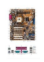
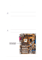
1.4 Motherboard Components Before installing the P4T533 motherboard, take time to familiarize yourself with its configuration: understanding the motherboard makes upgrading easy. Sufficient knowledge of specifications prevents accidental damage. Processor Support Chipsets Main Memory Expansion Slots Major System I/O Hardware Monitoring Special Feature Network Feature Audio Features Power Form Factor Location Socket 478 for Intel® P4™ Processors 2 Feature setting DSW1 External Frequency Selection 9 Feature setting DSW Clock Multiplier 15 Intel 850E North Bridge 3 Intel® ICH2 South Bridge 12 Multi-I/O Controller 13 4Mbit Programmable Flash EEPROM 19 Promise® RAID / ATA-133 Controller 22 USB 2.0 Controller 23 2 32-bit PC1066/800 Memory RIMMs 4 6 PCI Slots 27 Accelerated Graphics Port (AGP) Pro Slot 32 Floppy Disk Drive Connector 8 2 IDE Connectors (UltraDMA/133 Support 10 2 IDE Connectors (RAID Support 14 Smart Card Connector 16 iPanel / Infrared Connector 17 System Panel Connector 18 USB Headers (USB1.1 20 USB Headers (USB2.0 21 Game Header 31 PS/2 Mouse Connector green) 33 Parallel Port 34 USB 2.0 Connectors (Port 3/4 39 2 Serial Ports (COM1/2 40 USB 1.1 Connectors (Port 1/2 41 PS/2 Keyboard Connector purple) 42 System Voltage Monitor (integrated in ASUS ASIC 11 Onboard LED 24 Onboard AGP Warning LED 7 Modem Connector 29 RJ45 Connector (optional 35 (Audio Models Only) S/PDIF Connector 25 Audio Controller Chipset 26 Audio Connectors 30 Front Panel Audio Header 28 Line In Connector light blue) 36 Line Out Connector lime) 37 Microphone Connector pink) 38 AUX12V1 EZ PLUG Power Supply Connector 5 ATX Power Supply Connector 6 ATX12V Power Supply Connector 1 ATX 4 Chapter 1: Product introduction
-
 1
1 -
2
-
3
-
4
-
5
-
6
-
7
-
8
-
9
-
10
-
 11
11 -
 12
12 -
 13
13 -
 14
14 -
 15
15 -
 16
16 -
 17
17 -
 18
18 -
 19
19 -
 20
20 -
 21
21 -
22
-
23
-
24
-
25
-
26
-
27
-
28
-
29
-
30
-
31
-
32
-
33
-
34
-
35
-
36
-
37
-
38
-
39
-
40
-
41
-
42
-
43
-
44
-
45
-
46
-
47
-
48
-
49
-
50
-
51
-
52
-
53
-
54
-
55
-
56
-
57
-
58
-
59
-
60
-
61
-
62
-
63
-
64
-
65
-
66
-
67
-
68
-
69
-
70
-
71
-
72
-
73
-
74
-
75
-
76
-
77
-
78
-
79
-
80
-
81
-
82
-
83
-
84
-
85
-
86
-
87
-
88
-
89
-
90
-
91
-
92
-
93
-
94
-
95
-
96
-
97
-
98
-
99
-
100
-
101
-
102
-
103
-
104
-
105
-
106
-
107
-
108
-
109
-
110
-
111
-
112
-
113
-
114
-
115
-
116
-
117
-
118
-
119
-
120
-
121
-
122
-
123
-
124
-
125
-
126
-
127
-
128
-
129
-
130
-
131
-
132
-
133
-
134
-
135
-
136
 |
 |
