Asus P4T533 P4T533 User Manual - Page 51
ASUS P4T533 motherboard user guide, Floppy disk drive connector 34-1 pin FLOPPY, Power, CPU - cpu support
 |
View all Asus P4T533 manuals
Add to My Manuals
Save this manual to your list of manuals |
Page 51 highlights
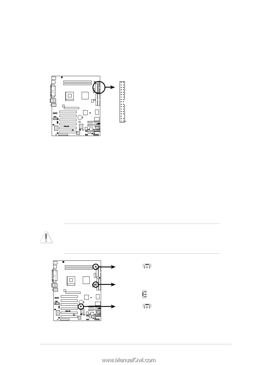
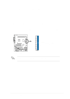
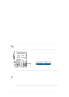
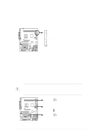
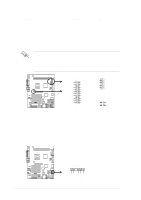
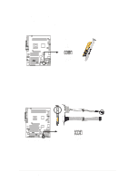
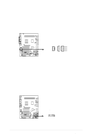
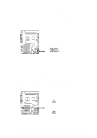
11. Floppy disk drive connector (34-1 pin FLOPPY) This connector supports the provided floppy drive ribbon cable. After connecting one end to the motherboard, connect the other end to the floppy drive. (Pin 5 is removed to prevent incorrect insertion when using ribbon cables with pin 5 plug). FLOPPY NOTE: Orient the red markings on the floppy ribbon cable to PIN 1. P4T533 ® PIN 1 P4T533 Floppy Disk Drive Connector 12. Power, CPU and Chassis Fan Connectors (Three 3-pin PWR_, CPU_, CHA_FAN) The two fan connectors support cooling fans of 350mA (4.2 Watts) or a total of 1A (12W) at +12V. Orient the fans so that the heat sink fins allow air flow to go across the onboard heat sinks instead of the expansion slots. The fan wiring and plug may vary depending on the fan manufacturer. Connect the fan cable to the connector matching the black wire to the ground pin. Do not forget to connect the fan cables to the fan connectors. Lack of sufficient air flow within the system may damage the motherboard components. These are not jumpers! DO NOT place jumper caps on the fan connectors! PWRFAN Rotation +12V GND CPU_FAN GND +12V Rotation P4T533 ® CH_FAN Rotation +12V GND P4T533 12-Volt Fan Connectors ASUS P4T533 motherboard user guide 37
-
 1
1 -
2
-
3
-
4
-
5
-
6
-
7
-
8
-
9
-
10
-
11
-
12
-
13
-
14
-
15
-
16
-
17
-
18
-
19
-
20
-
21
-
22
-
23
-
24
-
25
-
26
-
27
-
28
-
29
-
30
-
31
-
32
-
33
-
34
-
35
-
36
-
37
-
38
-
39
-
40
-
41
-
42
-
43
-
44
-
45
-
 46
46 -
 47
47 -
 48
48 -
 49
49 -
 50
50 -
 51
51 -
 52
52 -
 53
53 -
 54
54 -
 55
55 -
 56
56 -
57
-
58
-
59
-
60
-
61
-
62
-
63
-
64
-
65
-
66
-
67
-
68
-
69
-
70
-
71
-
72
-
73
-
74
-
75
-
76
-
77
-
78
-
79
-
80
-
81
-
82
-
83
-
84
-
85
-
86
-
87
-
88
-
89
-
90
-
91
-
92
-
93
-
94
-
95
-
96
-
97
-
98
-
99
-
100
-
101
-
102
-
103
-
104
-
105
-
106
-
107
-
108
-
109
-
110
-
111
-
112
-
113
-
114
-
115
-
116
-
117
-
118
-
119
-
120
-
121
-
122
-
123
-
124
-
125
-
126
-
127
-
128
-
129
-
130
-
131
-
132
-
133
-
134
-
135
-
136
 |
 |