Asus P4T533 P4T533 User Manual - Page 60
ATX Power Switch / Soft-Off Switch Lead 2 pin PWRSW - c set up diagram
 |
View all Asus P4T533 manuals
Add to My Manuals
Save this manual to your list of manuals |
Page 60 highlights
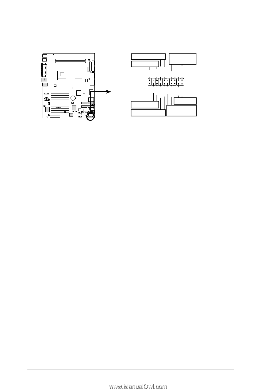
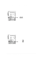
Panel Connector (20 pin PANEL) The following diagram illustrates items 27-33: Keyboard Lock Speaker Power LED Connector +5 V PLED Keylock Ground +5V Ground Ground Speaker +5 V MLED ExtSMI# Ground PWR Ground Reset Ground P4T533 ® P4T533 System Panel Connectors Message LED SMI Lead Reset SW ATX Power Switch* * Requires an ATX power supply. 27. System Power LED Lead (3-1 pin PLED) This connector supplies the system power LED. The LED lights up when the system power is on, and the LED blinks when the system is in sleep or soft-off mode. 28. Keyboard Lock Switch Lead (2 pin KEYLOCK) This 2-pin connector supplies the case-mounted key switch for keyboard locking. 29. System Warning Speaker Lead (4 pin SPEAKER) This connector supplies the case-mounted speaker to sound system beeps and warnings. 30. System Message LED Lead (2 pin MLED) This connector supports the system message LED to indicate receipt of messages from a fax/modem. The normal status for this LED is ON, when there is no incoming data signal. The LED blinks when data is received. The system message LED feature requires an ACPI OS and driver support. 31. System Management Interrupt Lead (2 pin SMI) This connector permits switching to suspend mode, or "Green" mode: system activity is decreased to conserve power and system components. Attach the case-mounted suspend switch this 2-pin connector. 32. ATX Power Switch / Soft-Off Switch Lead (2 pin PWRSW) The system power is controlled by a momentary switch attached to this connector. Pressing the button switches the system between ON and SLEEP, or ON and SOFT OFF, depending on the BIOS or OS settings. Pressing the button while in the ON mode for more than 4 seconds turns the system off. 33. Reset Switch Lead (2-pin RESET) This connector supports the case-mounted reset switch for rebooting the system without turning off the power switch. 46 Chapter 2: Hardware information
-
 1
1 -
2
-
3
-
4
-
5
-
6
-
7
-
8
-
9
-
10
-
11
-
12
-
13
-
14
-
15
-
16
-
17
-
18
-
19
-
20
-
21
-
22
-
23
-
24
-
25
-
26
-
27
-
28
-
29
-
30
-
31
-
32
-
33
-
34
-
35
-
36
-
37
-
38
-
39
-
40
-
41
-
42
-
43
-
44
-
45
-
46
-
47
-
48
-
49
-
50
-
51
-
52
-
53
-
54
-
 55
55 -
 56
56 -
 57
57 -
 58
58 -
 59
59 -
 60
60 -
 61
61 -
 62
62 -
 63
63 -
 64
64 -
 65
65 -
66
-
67
-
68
-
69
-
70
-
71
-
72
-
73
-
74
-
75
-
76
-
77
-
78
-
79
-
80
-
81
-
82
-
83
-
84
-
85
-
86
-
87
-
88
-
89
-
90
-
91
-
92
-
93
-
94
-
95
-
96
-
97
-
98
-
99
-
100
-
101
-
102
-
103
-
104
-
105
-
106
-
107
-
108
-
109
-
110
-
111
-
112
-
113
-
114
-
115
-
116
-
117
-
118
-
119
-
120
-
121
-
122
-
123
-
124
-
125
-
126
-
127
-
128
-
129
-
130
-
131
-
132
-
133
-
134
-
135
-
136
 |
 |