Asus P4T533 P4T533 User Manual - Page 50
Hardware information, Primary RAID IDE Blue / Secondary RAID IDE Black IDE, Connectors
 |
View all Asus P4T533 manuals
Add to My Manuals
Save this manual to your list of manuals |
Page 50 highlights
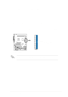
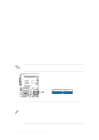
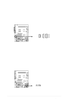
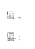
10. Primary RAID IDE (Blue) / Secondary RAID IDE (Black) IDE Connectors (Two 40-1 pin PRI_RAID and SEC_RAID) The P4T533 motherboard is supplied with two extra onboard IDE connectors: one Promise IDE1 and one Promise IDE2. Use them to setup the RAID 0 or 1 arrays and to support extra ATAPI devices. A total of eight hard-disks, two on each IDE connector, can be connected to the A7V333; but, only two can function in a RAID array. See 5.4 Software Setup for more information about setting up a RAID array. The Primary and Secondary RAID IDE connectors support the IDE hard disk ribbon cables supplied with the motherboard. Connect the cable's blue connector to the motherboard's primary IDE connector (recommended) or the secondary IDE connector. Connect the opposite end of the cable to your UltraDMA133/100/66 device (hard disk drive). If a second hard disk drive is connected, you may reset its jumper to Slave or Master/Slave mode. NonUltraDMA133/100/66 devices should be connected to the secondary IDE connector. BIOS supports specific device bootup (see 4.6 Boot Menu.) UltraDMA/133 is backward compatible with DMA100/66/33 and with all with existing DMA devices and systems. IMPORTANT! UltraDMA100 and UltraDMA133 IDE devices require a 40-pin 80-conductor cable and RAID arrays only operate with such cables. NOTE: Orient the red markings (usually zigzag) on the IDE ribbon cable to PIN 1. P4T533 ® P4T533 RAID Connectors SEC_RAID PIN 1 PRI_RAID NOTE! For high-performance and RAID 0 or 1 set ups, always setup two hard disks with two separate ribbon cables, one for the primary IDE connector and another for the secondary IDE connector. Usually, both disks must be set to the Master settings. Also, you may install one operating system on an IDE drive and another on a SCSI drive and select the boot disk through BIOS. (See 4.6 Boot Menu.) Do not connect any other types of IDE devices to the Promise IDE connectors; they support hard disk drive devices only. 36 Chapter 2: Hardware information
-
 1
1 -
2
-
3
-
4
-
5
-
6
-
7
-
8
-
9
-
10
-
11
-
12
-
13
-
14
-
15
-
16
-
17
-
18
-
19
-
20
-
21
-
22
-
23
-
24
-
25
-
26
-
27
-
28
-
29
-
30
-
31
-
32
-
33
-
34
-
35
-
36
-
37
-
38
-
39
-
40
-
41
-
42
-
43
-
44
-
 45
45 -
 46
46 -
 47
47 -
 48
48 -
 49
49 -
 50
50 -
 51
51 -
 52
52 -
 53
53 -
 54
54 -
 55
55 -
56
-
57
-
58
-
59
-
60
-
61
-
62
-
63
-
64
-
65
-
66
-
67
-
68
-
69
-
70
-
71
-
72
-
73
-
74
-
75
-
76
-
77
-
78
-
79
-
80
-
81
-
82
-
83
-
84
-
85
-
86
-
87
-
88
-
89
-
90
-
91
-
92
-
93
-
94
-
95
-
96
-
97
-
98
-
99
-
100
-
101
-
102
-
103
-
104
-
105
-
106
-
107
-
108
-
109
-
110
-
111
-
112
-
113
-
114
-
115
-
116
-
117
-
118
-
119
-
120
-
121
-
122
-
123
-
124
-
125
-
126
-
127
-
128
-
129
-
130
-
131
-
132
-
133
-
134
-
135
-
136
 |
 |
