Canon PowerShot G5 Service Manual
Canon PowerShot G5 Manual
 |
View all Canon PowerShot G5 manuals
Add to My Manuals
Save this manual to your list of manuals |
Canon PowerShot G5 manual content summary:
- Canon PowerShot G5 | Service Manual - Page 1
- Canon PowerShot G5 | Service Manual - Page 2
laws, this manual may not be copied, reproduced, published (including on the World Wide Web) or translated into another language, in whole or in part, without the written consent of Canon Inc.. Copyright © 2003 by Canon Inc. CANON INC. Digital Imaging Products Service Dept. 30-2, Shimomaruko - Canon PowerShot G5 | Service Manual - Page 3
special safety-related characteristics, always use genuine CANON replacement parts. Especially critical parts in the power circuit block should not be replaced with other makes. Critical parts are marked with ! in the schematic diagrams. 2. When servicing, observe the original lead dress. If a short - Canon PowerShot G5 | Service Manual - Page 4
-Battery Charger (CG-570) sharing compatibility with Canon digital video camcorders 1-12 3 Exterior 3-1 Exterior Photos 1-13 3-2 6-dimensional diagram 1-14 3-3 Nomenclature 1-15 3-4 UI Information 1-16 4 Specifications 4-1 Camera Specifications 1-20 4-2 Function's Availability and Data memory - Canon PowerShot G5 | Service Manual - Page 5
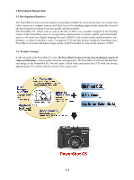
enhancements in picture quality and functionality such as a 4x zoom lens, Digital Imaging Processor (DIGIC), and second-curtain synchronization. Furthermore, we plan to introduce a new 5-megapixel CCD into this product design for launching a new PowerShot G5 model with higher image quality in the - Canon PowerShot G5 | Service Manual - Page 6
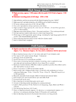
with slow shutter speed Exif 2.2 (Exif Print) compliant Full Features Digital zoom function with continuously changing angle of view (Approx. 4.1x : Maximum of approx. 16x when used in combination with the optical zoom) Macro function focuses close to 5 cm (wide-end) and 15 cm (telephoto-end) Two - Canon PowerShot G5 | Service Manual - Page 7
(QVGA/QQVGA) Manual setting functions designed to meet user needs (Focus, Shutter speed and Aperture value, Flash output, Exposure compensation) AF, AE and FE lock function Magnified replay for convenient image confirmation (from approx. 2x to 10x zoom) (Also available during rec-review) IO sensor - Canon PowerShot G5 | Service Manual - Page 8
Exterior Black body that symbolizes "High level" Refer to 1-3 Desigh Concept System Accessories Lithium- ion battery charger that can also be used with EOS DIGITAL (CB- 5L) Battery pack charger that can also be used with Canon digital video camcorders (CG- 570) Tele-converter (with up to 245 mm - Canon PowerShot G5 | Service Manual - Page 9
PowerShot G3 (advancement to five megapixels) --> Providing a sleek, sharp-looking image as a better high-performance camera -Black body The body uses the aluminum cover from the PowerShot at the lens edge to enhance the metallic feel. The metallic accents in the black body give the camera a more - Canon PowerShot G5 | Service Manual - Page 10
1-6 - Canon PowerShot G5 | Service Manual - Page 11
1-7 - Canon PowerShot G5 | Service Manual - Page 12
1-8 - Canon PowerShot G5 | Service Manual - Page 13
of approx. 5.3 megapixels) Number of recording pixels : 2592 x 1944 The PowerShot G5 incorporates a CCD sensor with approx. 5.0-mega camera effective pixels in camera mode (total of approx. 5.3-mega pixels), giving it the greatest number of pixels in the compact camera class. This CCD - Canon PowerShot G5 | Service Manual - Page 14
function with continuously changing angle of view (Maximum of approximately 16x when used in combination with the optical zoom) The digital zoom magnification of the PowerShot G5 increases from approx. 3.6x, employed on PowerShot G3 to approx. 4.1x owing to employment of 5M-pixel CCD. The field - Canon PowerShot G5 | Service Manual - Page 15
the PowerShot G3 supports PTP, a standard protocol, driver-less image communications with computers are possible when combined with recent operating systems (Windows XP or Mac OS X (version 10.1/10.2)). Futhermore computer-controlled camera functions have been added to the PowerShot G5 (Additional - Canon PowerShot G5 | Service Manual - Page 16
CG-570) sharing compatibility with Canon digital video camcorders The PowerShot G5 battery pack (BP-511/512) can also be used with the Battery Charger (CG-570) developed for Canon digital video camcorders. With the CG-570 charger, batteries are charged by using with the Compact Power Adapter (CA-560 - Canon PowerShot G5 | Service Manual - Page 17
3 Exterior 3-1 Exterior Photos Photo 3-1 PowerShot G5 Front Photo 3-2 PowerShot G5 Back Photo 3-3 PowerShot G5 setup Tele-converter Photo 3-4 PowerShot G5 setup Wide Converter Photo 3-5 Setup Speedlite 550EX Photo 3-6 Setup Macro Ring Lite MR-14EX 1-13 Photo 3-6 Setup Macro Twin Lite MT-24EX - Canon PowerShot G5 | Service Manual - Page 18
3-2 6-dimensional diagram 121.0 (4.76) 69.9 (2.75) 43.5 (1.71) CANON ZOOM LENS 7.2-28.8mm 1:2.0-3.0 71.7 (2.82) 73.9 (2.91) 122.0 (4.80) 1-14 Unit: mm (inch) - Canon PowerShot G5 | Service Manual - Page 19
3-3 Nomenclature Indicator LCD monitor 1-15 - Canon PowerShot G5 | Service Manual - Page 20
Slow Synchro >On >Off Flash Adjust >Auto >Manual Red>eye >On >Off Cont. Shooting (Standard) (High speed) Self>timer >10seconds >2 seconds Wireless Delay >0 seconds >2 seconds >10 seconds 1-16 Spot AE Point >Center >AF Point ND filter >On >Off MF>Point Zoom >On >Off AF Mode >Continuous - Canon PowerShot G5 | Service Manual - Page 21
Intervalom eter >> S ave S ettings >> 1-17 - Canon PowerShot G5 | Service Manual - Page 22
>Replay Menu Protect >> Rotate >> Erase all >> Slide Show >> Print Order >> Transfer Order >> >My Camera Menu >Theme >Start- up Image >Start- up Sound >Operation Sound >Selftimer Sound >Shutter Sound 1-18 - Canon PowerShot G5 | Service Manual - Page 23
>Set up Menu Beep >On >Off LCD Brightness >Nomal >Bright Auto Power Down >On >Off Date/Time >> Format >> Shutter Volume >Off to 5 Playback Vol.(Replay) >Off to 5 Start>up Vol. >Off to 5 Operation Vol. >Off to 5 Selftimer Vol. >Off to 5 File No.Reset >On >Off Auto Rotate >On >Off Distance Units - Canon PowerShot G5 | Service Manual - Page 24
4-1 Camera Specifications Image sensor (CCD) Camera effective pixels Total pixels Transfer method Chip size Aspect ratio Filter type Approx. 5.0 M pixels Approx. 5.3 M pixels Interline 1/1.8 in. 4:3 Primary color filter (Beyer type) Lens Focal length f/number Lens construction Optical zoom - Canon PowerShot G5 | Service Manual - Page 25
increments Manual flash output setting 3 steps (strong [100 % flash] / normal / low) FE lock Available Slow-sync. Available Second curtain Available Flash (External) Flash contacts Sync-terminals at accessory shoe Recommended flashes Canon SPEEDLITE 220EX, 380EX, 420EX, 550EX Macro-Ring - Canon PowerShot G5 | Service Manual - Page 26
Manual / Custom1 / Custom2) / Programmed image control zone (Portrait / Landscape / Night Scene / Stitch Assist / Movie) Shooting functions Digital zoom Photo effects Image quality adjustment Approx. 4.1x (Maximum of approx. 16x zoom Review Camera according to the CF card capacity.) Operates with - Canon PowerShot G5 | Service Manual - Page 27
Recording specifications File format Design rule for Camera File system Digital Print Canon's testing standard and may vary depending on the scene, subjects or camera settings. CompactFlashTM (CF) card (Type I or Type II ) FAT12 / FAT16 and FAT32 * When formating with the camera - Canon PowerShot G5 | Service Manual - Page 28
sound and Self-timer sound *Each item can be created by users with the camera. Item s Start-up image Start-up sound Shutter sound Operation sound Self-timer sound File size 20 KB 10.9 KB 3.36 KB 3.36 KB 21.7 KB specifications 320x240 pixels, JPEG file with 4: 2 : 0 or 4: 2 :2, Aspect ratio of - Canon PowerShot G5 | Service Manual - Page 29
at wide angle and at telephoto end alternately with 20 seconds intervals. Use flash at every fourth shot. Turn camera off and on at every eight shot. Replay time Approx. 360 min. Under Canon standard conditions: Using BP-511. Normal temperature (23 C). Repeat replay automatically at a speed - Canon PowerShot G5 | Service Manual - Page 30
4-2 Function's Availability and Data memory in Each Shooting Mode 1-26 - Canon PowerShot G5 | Service Manual - Page 31
1-27 - Canon PowerShot G5 | Service Manual - Page 32
1-28 - Canon PowerShot G5 | Service Manual - Page 33
4-4 Accessory Specifications -Battery Charger (CB-5L) Use for : BP-511 / BP-512 Rated input C Dimensions : 73.0 x 93.0 x 36.0 mm (2.9 x 3.7 x 1.4 in.) Weight : Approx. 130 g (4.6 oz.) -Compact power adapter (CA-570) Use for : BP-511 / BP-512 Rated input : AC 100 - 240V (50/60 Hz) 29 - Canon PowerShot G5 | Service Manual - Page 34
1-30 - Canon PowerShot G5 | Service Manual - Page 35
1-31 - Canon PowerShot G5 | Service Manual - Page 36
1-32 - Canon PowerShot G5 | Service Manual - Page 37
NS-DC2 FC-32M CF Card FC-32M (*2) Canon Digital Camera ArcSoft Camera Solution Disk Suite CD-ROM Lens Cap USB Interface Cable IFC-300PCU (*2) for PC and Macintosh Wireless Controller WL-DC100 (*2) PowerShot G5 Lithium Battery CR2025 for Wireless Controller WL-DC100 Battery Pack BP-511 - Canon PowerShot G5 | Service Manual - Page 38
Block Diagram 2-2 2.1.2 Power Supply Control Sequence 2-2 2.2 Signal Processing 2-3 2.2.1 System Control 2-3 2.2.2 Picture Processing 2-4 2.2.3 Audio Processing (Recording and Playback Functions 2-4 3. Troubleshooting 2-5 3.1 When an Error Code is Displayed 2-5 3.2 When a Problem Occurs 2-7 - Canon PowerShot G5 | Service Manual - Page 39
signal to the digital signal. 3) from the CF card using DSP. ( Battery charging control circuit. 1.3 LCD PCB ASS'Y 1) Image display. 2) Backlight for LCD drive. 1.4 TOP MODULE UNIT 1) Operation switch, operation display and finder LED. 1.5 EF FPC 1) Flash control. 1.6 STJ PCB ASS'Y 1) Flash - Canon PowerShot G5 | Service Manual - Page 40
E2, E3 CONTROL MAIN PCB ASS'Y CPU DSP E4 E21 D14 DC-IN BATTERY CHARGE CONTROL Q54 Q22 DC/DC CONVERTER E0 OUTPUT E1 OUTPUT E2 OUTPUT E3 Block Diagram 2.1.2 Power Supply Control Sequence 1) In the case of either "Battery is Installed" or External Power is Supplied to "DC-IN" connector; CPU - Canon PowerShot G5 | Service Manual - Page 41
2. TECHNICAL DESCRIPTION 2.2 Signal Processing MAIN PCB ASS'Y LENS Drive Pulse CCD Sensor SDRAM HD, VD CLK TG CDS, A/D DSP Motor Driver AF Support LED FINDER LED LCD Driver Video Amp FLASH MEMORY MIC Electric FLASH RTC MIC Amp CPU Audio Amp BUZZER CF card LCD AV OUT USB SPEAKER SW DIAL - Canon PowerShot G5 | Service Manual - Page 42
picture is converted to the signal processing and the digital data by the CDS and A/D converter, and is sent to the card. • Outputs the picture data to the CPU. • Outputs analog video signal to the LCD and VIDEO OUT. 3) The video signal that is supplied form the DSP is controlled by the LCD driver - Canon PowerShot G5 | Service Manual - Page 43
LENS ZOOM LENS ERROR Occurrence Conditions AF processing did not end within the specified time. The focus lens was not driven. Auto Flash Control The lens barrel is fed out with the lens cap attached → Remedy: Remove the lens cap, and restart the camera. OPTICAL UNIT MAIN PCB ASS'Y Either zoom - Canon PowerShot G5 | Service Manual - Page 44
TIME OVER POWER OFF ERROR CF FORMAT ERROR QUICK REVIEW ERROR Occurrence Conditions When the CF becomes full during writing of CARD/MICRO DRIVE MAIN PCB ASS'Y The battery or DC plug was removed while the image was being recorded to the CF Card/Micro Drive. → Remedy: Restart the camera. CF CARD - Canon PowerShot G5 | Service Manual - Page 45
" Problem (when an error code is not displayed) The camera does zoom does not function. The Display Panel (B/W LCD) is strange. The Built-in Flash does not fire. Cause and Probable Faulty Part DC/DC CONVERTER PCB ASS'Y MAIN PCB ASS'Y MAIN DIAL BRUSH TOP MODULE UNIT BATTERY BOX MAIN UNIT BATTERY - Canon PowerShot G5 | Service Manual - Page 46
CHAPTER 2. TECHNICAL DESCRIPTION Problem (when an error code is not displayed) The External Flash does not fire. Video output is strange. Communications with the personal computer is not possible. The CF card or Micro Drive is not recognized. Sound cannot be recorded. Shutter sound/Sound is not - Canon PowerShot G5 | Service Manual - Page 47
INSTRUCTION CONTENTS 1. Before Starting the Repair Work 1.1 Precaution on Flash High Tension Circuit 3-1 1.2 List of Tools 3-1 1.3 List of Supplies 3-1 1.4 Flexible Connectors 3-2 2. Disassembly/Assembly 2.1 Procedure 3-3 2.2 Removal 21 2.3.1.4 ZOOM LEVER UNIT 3-22 2.3.1.5 ACCESSORY CONTACT - Canon PowerShot G5 | Service Manual - Page 48
3-35 3.3 Before Starting Electrical Adjustments 3-36 3.3.1 TWAIN Driver Installation 3-36 3.3.2 Factory Mode Driver Installation 3-36 3.3.3 Adjustment Software Installation 3-38 3.3.4 Preparation 3-39 3.3.5 Starting up the Adjustment Software 3-40 3.3.6 Menu Window 3-40 3.3.7 How to Use - Canon PowerShot G5 | Service Manual - Page 49
INSTRUCTION 1. Before Starting the Repair Work Be sure to read the following precaution before starting the repair work. 1.1 Precaution on Flash High Tension Circuit • When the FRONT COVER UNIT is removed used for the re-assembling during service. (1) List of supplies New ZOOM LEVER UNIT ACC. SHOE - Canon PowerShot G5 | Service Manual - Page 50
Type D and Type E, set them to the unlocked state before removing and inserting flexible card. After flexible card is inserted, set them to the locked state. 2. The flexible card is equipped with the holes as shown. Use them for removal and insertion by inserting the tweezers into them as required - Canon PowerShot G5 | Service Manual - Page 51
REPAIR INSTRUCTION 2. Disassembly/Assembly 2.1 Procedure Disassembling procedure of PowerShot G5 is shown by the following flowchart. Reverse the disassembling procedure to reassemble them. ∗ The pages to refer are shown in parenthesis ( ). FRONT COVER UNIT (3-4) REAR COVER UNIT (3-5) BATTERY - Canon PowerShot G5 | Service Manual - Page 52
CHAPTER 3. REPAIR INSTRUCTION 2.2 Removal of Main Parts/Units Alignment position (1)-6 Button (1)-6 FRONT COVER UNIT h (1)-3 g (1)-2 (1)-6 (1)-4 e (1)-5 d (1)-7 FRONT COVER UNIT (1)-1 FRONT CAP UNIT e CD1-5030-000 h CD1-5033-000 g CD1-5032-000 d - Canon PowerShot G5 | Service Manual - Page 53
3. REPAIR INSTRUCTION CAUTION Be careful dial Rotate the diopter adjustment dial in the direction of mark A as far as it can go. When it Remove the three screws of e. 2. Remove the screw of f. 3. Open the CF COVER. 4. Open the EVF UNIT. 5. Remove the REAR COVER UNIT from the main body. 6. Remove - Canon PowerShot G5 | Service Manual - Page 54
-9170-359 3.5mm BLACK M1.7 (SELF TAP) Fig. 3-6 BATTERY LID UNIT, DATE BATTERY HOLDER 2.2.3 BATTERY LID UNIT, DATE BATTERY HOLDER (1) BATTERY LID UNIT 1. Remove the screw of q. 2. Remove the BATTERY SHAFT HOLDER. 3. Release the lock by sliding the BATTERY LID HOLDER, and open it. 4. Push out the - Canon PowerShot G5 | Service Manual - Page 55
CF COVER CHAPTER 3. REPAIR INSTRUCTION NOTE2 (Assembling) (2)-3 While being careful not to ooze , CF COVER METAL M1.7 (SELF TAP) 2.2.4 SIDE COVER, CF COVER (1) SIDE COVER 1. Remove the screw of f. 2. Remove the SIDE COVER. 3. Push out the JACK COVER SHAFT with the thin stick like tweezers, and - Canon PowerShot G5 | Service Manual - Page 56
3. REPAIR INSTRUCTION r (1)-3 (1)-4 m (1)-2 STRAP RIGHT BASE (1)-1n (1)-8 (1)-7 Dowel (1)-5 TOP COVER (1)-6 m XA1-7170-307 n XA1-7170-357 r XA4-9170-407 3.0mm 3.5mm 4.0mm METAL M1.7 Fig. 3-8 TOP COVER METAL M1.7 METAL M1.7 (SELF TAP) 2.2.5 TOP COVER (1) TOP COVER 1. Remove the screw - Canon PowerShot G5 | Service Manual - Page 57
CHAPTER 3. REPAIR INSTRUCTION NOTE (Assembling) (1)-4 Insulation tape SIDE COVER FRAME (1)-1 q Dowels (1)-4 (1)-3 2.2.6 SIDE COVER FRAME (1) SIDE COVER FRAME 1. Remove the screw of q. 2. Remove the screw of b. 3. Remove the two dowels and remove the SIDE COVER FRAME. 4. Peel off the Insulation - Canon PowerShot G5 | Service Manual - Page 58
CHAPTER 3. REPAIR INSTRUCTION CAUTION Never touch the terminals of the capacitor ! Be sure to discharge from the groove of the MAIN BARREL UNIT. 3. Remove the two screws of m. 4. Remove the screw of q. 5. Remove the MAIN BARREL UNIT. CAUTION Remove it with utmost care not to touch the terminal of - Canon PowerShot G5 | Service Manual - Page 59
white yellow MAIN PCB ASS'Y (1)-1 (1)-2 CHAPTER 3. REPAIR INSTRUCTION NOTE2 (Assembling) (1)-6 SUB FRAME MAIN PCB ASS'Y (1)-5 /FLASH FPC. 3. Remove the two screws of j. 4. Disconnect the connector of the DC/DC CONVERTER PCB ASS'Y. 5. Remove the three cables from the EVF UNIT. 6. Remove - Canon PowerShot G5 | Service Manual - Page 60
CHAPTER 3. REPAIR INSTRUCTION Dowels SUB FRAME EVF UNIT (2)-1 c (2)-2 (1)-1 c (1)-4 NOTE (Assembling) (1)-3 (1)-5 (1)-3 direction of the arrow. 2. Remove the two screws of i. 3. Remove the two claws and remove the HINGE COVER. 4. Remove the two screws of c. 5. Remove the EVF UNIT. NOTE ( - Canon PowerShot G5 | Service Manual - Page 61
EF SENSOR of the (1)-5 REAR PLATE UNIT Dowels CHAPTER 3. REPAIR INSTRUCTION (1)-2 q (1)-2 q k (1)-3 REAR PLATE UNIT (1)-6 (1)-1 Dowels (2)-3 m Remove the flexible board of the HV MODULE UNIT. 2. Remove the three screws of q. 3. Remove the two screws of k. 4. Remove the screw of m. 5. Remove - Canon PowerShot G5 | Service Manual - Page 62
-sided adhesive tape a CB1-1998-000 (1)-5 q q XA4-9170-359 3.0mm 3.5mm METAL M1.7 BLACK M1.7 (SELF TAP) Fig. 3-14 FLASH/JACK UNIT, SPEAKER UNIT 2.2.11 FLASH/JACK UNIT, SPEAKER UNIT (1) FLASH/JACK UNIT 1. Remove the MAIN/FLASH FPC. 2. Remove the cable of the BAT BOX UNIT and two cables of the - Canon PowerShot G5 | Service Manual - Page 63
UNIT/FINDER UNIT to the direction of the arrow. 5. Remove the CCD SPRING from the OPTICAL UNIT/FINDER UNIT. CAUTION Be careful not to drop the CCD SPRING. NOTE1 (Assembling) When installing the ZOOM GND PLATE, align it with the mark used for position setting of the MAIN FRAME. NOTE2 (Assembling - Canon PowerShot G5 | Service Manual - Page 64
CHAPTER 3. REPAIR INSTRUCTION (1)-4 (1)-5 Flat-head screwdriver (1)-6 LED HOLDER (1)-6 (1)-6 FINDER UNIT q (1)-1 (1) OPTICAL UNIT, FINDER UNIT 1. Remove the two screws of q. 2. Slant the FINDER UNIT in the direction of the arrow, and remove the dowel. 3. Remove the claw on the opposite side. - Canon PowerShot G5 | Service Manual - Page 65
Hole Cutout CHAPTER 3. REPAIR INSTRUCTION (1)-2 A Rotate the gear in the direction of mark A as far as it can not set in the retracted position, remove the CCD HOLDER UNIT (refer to page 3-28) and rotate the portion B of the OPTICAL UNIT in the direction of mark C with hands until the OPTICAL UNIT - Canon PowerShot G5 | Service Manual - Page 66
3. REPAIR INSTRUCTION m (1)-2 (1)-3 (2)-2 TRIPOD BASE BAT BOX UNIT (1)-2 m MAIN FRAME (1)-1 q (2)-1 m m XA1-7170-307 q XA4-9170-359 3.0mm 3.5mm METAL M1.7 Fig. 3-18 BAT BOX UNIT, TRIPOD BASE BLACK M1.7 (SELF TAP) 2.2.15 BAT BOX UNIT, TRIPOD BASE (1) BAT BOX UNIT 1. Remove the screw - Canon PowerShot G5 | Service Manual - Page 67
Main Units q B/W LCD UNIT (1)-3 l (1)-1 CHAPTER 3. REPAIR INSTRUCTION NOTE (Assembling) B/W LCD UNIT A ACC FPC p (1)-2 (2)-3 LCD UNIT 1. Remove the two screws of l. 2. Remove the two screws of p. 3. Remove the screw of q. 4. Remove the claw and remove the B/W LCD UNIT. 5. Remove the STRAP - Canon PowerShot G5 | Service Manual - Page 68
CHAPTER 3. REPAIR INSTRUCTION (1)-1 DUST COVER SEAL NOTE (Assembling) (1)-2 B/W LCD WINDOW Fig. 3-20 B/W LCD WINDOW 2.3.1.2 B/W LCD WINDOW (1) B/W LCD WINDOW 1. Peel off the DUST COVER SEAL. 2. Remove the B/W LCD WINDOW. NOTE (Assembling) Install the DUST COVER SEAL as shown in the illustration. 3- - Canon PowerShot G5 | Service Manual - Page 69
INSTRUCTION NOTE1 (1)-4 MODE DIAL BALL (1)-5 MODE DIAL SPRING NOTE3 (Assembling) ZOOM LEVER (1)-4, (1)-5 UNIT (1)-3 MODE DIAL BASE UNIT NOTE2 ( Remove the screw of q. 3. Remove the MODE DIAL BASE UNIT, then remove the MODE DIAL from the TOP COVER UNIT. 4. Remove the MODE DIAL BALL. 5. Remove the - Canon PowerShot G5 | Service Manual - Page 70
METAL M1.7 2.3.1.4 ZOOM LEVER UNIT (1) ZOOM LEVER UNIT 1. Remove the ZOOM SPRING from the claw of the INNER COVER. 2. Remove the two screws of b. 3. Remove the ZOOM BRUSH and the ZOOM SPRING from the INNER COVER. 4. Remove the ZOOM LEVER UNIT. 5. Remove the ZOOM SPRING from the ZOOM BRUSH. CAUTION - Canon PowerShot G5 | Service Manual - Page 71
CAUTION Be careful not to damage the parts! (1)-4 ACCESSORY CONTACT UNIT (1)-4 Soldering Fig. 3-23 ACCESSORY CONTACT UNIT 2.3.1.5 ACCESSORY CONTACT UNIT (1) ACC. SHOE, ACC. SHOE SPRING 1. Insert a pair of tweezers under the ACC. SHOE SPRING and remove it. CAUTION Be careful not to damage the - Canon PowerShot G5 | Service Manual - Page 72
CHAPTER 3. REPAIR INSTRUCTION Blue White LCD PCB ASS'Y Blue (2)-3 (2)-2 (2)-2 (2)-1 m HINGE UNIT Yellow (1)-2 , HINGE UNIT (1) LCD TOP COVER 1. Remove the four screws of d. 2. Remove the LCD TOP COVER. (2) HINGE UNIT 1. Remove the screw of m. 2. Remove the cable of the HINGE UNIT (Two - Canon PowerShot G5 | Service Manual - Page 73
CHAPTER 3. REPAIR INSTRUCTION NUT PLATE q (1)-1 (1)-2 (2)-1 (1)-3 LCD PANEL NOTE (Assembling) In the case of the repair service part, it is supplied with the protection sheet. Remove the protection sheet before use. Dowels (2)-2 BACK LIGHT UNIT Dowels BASE PIN LCD FRAME COVER Fig. 3-25 LCD - Canon PowerShot G5 | Service Manual - Page 74
PCB ASS'Y (1) LCD PCB ASS'Y 1. Remove the soldering (Four places). 2. Remove the LCD PCB ASS'Y and the LCD SHEET from the BACK LIGHT UNIT. NOTE (Assembling) When LCD PCB ASS'Y is going to replace, take note of the two QR code numbers (10 digit and 8 digit hexadecimal numbers) of the replacement LCD - Canon PowerShot G5 | Service Manual - Page 75
CHAPTER 3. REPAIR INSTRUCTION Setting the position for reassembling Double-sided adhesive tape REAR the illustration. (2) EF SENSOR HOLDER 1. While peeling off the double-sided adhesive tape, remove the EF SENSOR HOLDER. NOTE2 (Assembling) When installing the EF SENSOR HOLDER, attach the double - Canon PowerShot G5 | Service Manual - Page 76
SHUTTER UNIT from the dowel of the FPC GUIDE . 4. Remove the FPC GUIDE. 5. Pinches the SHUTTER UNIT with fingers at marked by A, and rotate the SHUTTER UNIT as far as it can go in the direction of the arrow. 6. Remove the SHUTTER UNIT. 7. Remove the FRONT LENS UNIT from the LENS BARREL UNIT. 3-28 - Canon PowerShot G5 | Service Manual - Page 77
the CCD HOLDER, SHUTTER UNIT-1 (1) Assembling the CCD HOLDER,SHUTTER UNIT-1 1. Place the FRONT LENS UNIT on top of the LENS BARREL UNIT. 2. While pushing the FRONT LENS UNIT in the direction of mark A and rotating it in the direction of mark B as far as it can go. When it reaches the end, return it - Canon PowerShot G5 | Service Manual - Page 78
CHAPTER 3. REPAIR INSTRUCTION SHUTTER UNIT (1)-1 A FRONT LENS UNIT B NOTE1 (Assembling) (1)-1 (1)-2 LENS BARREL UNIT B CCD HOLDER UNIT Large projected part Dowel (1)-3 FPC GUIDE Flexible board of the SHUTTER UNIT (1)-4 Dowel FPC GUIDE NOTE2 (Assembling) (1)-5 Small projected part - Canon PowerShot G5 | Service Manual - Page 79
BAT BOX SUB UNIT (1)-2 CF CLIPPING1 SPRING CHAPTER 3. REPAIR INSTRUCTION NOTE1 (Assembling) (1)-7 q (1)-6 (1)-1 o (2)-2 R/C HOLDER (1)-7 Two places). (2) R/C HOLDER 1. Remove the screw of q. 2. Remove the R/C HOLDER. NOTE2 (Assembling) Route the cable of the BATTERY BOX SUB UNIT so that it - Canon PowerShot G5 | Service Manual - Page 80
CHAPTER 3. REPAIR INSTRUCTION HV MODULE UNIT SLT HOLDER NOTE (Assembling) Insert the HV MODULE UNIT, LEAF SW UNIT (1) HV MODULE UNIT 1. Remove the flexible board of the HV MODULE UNIT from the dowel. 2. Remove the four claws, then remove the SLT HOLDER from the SI sensor of the HV MODULE UNIT. - Canon PowerShot G5 | Service Manual - Page 81
M1.7 n XA1-7170-357 3.5mm METAL M1.7 q XA4-9170-359 3.5mm BLACK M1.7 (SELF TAP) r XA4-9170-407 4.0mm METAL M1.7 (SELF TAP) CHAPTER 3. REPAIR INSTRUCTION c CD1-3798-000 3.0mm METAL M1.7 g CD1-5032-000 4.0mm BLACK M1.7 (SELF TAP) k XA1-7170-147 1.4mm METAL M1.7 o XA4-5170-307 3.0mm METAL - Canon PowerShot G5 | Service Manual - Page 82
CHAPTER 3. REPAIR INSTRUCTION 3. Adjustments 3.1 Replacement Parts and Adjustment Items PowerShot G5 requires electrical adjustments when replacement. Adjustment Items CCD Replacement Part Adjustment BATTERY BOX UNIT DC/DC CONV. UNIT OPTICAL UNIT #1 FLASH UNIT MAIN PCB ASS'Y LCD PCB - Canon PowerShot G5 | Service Manual - Page 83
CHAPTER 3. REPAIR INSTRUCTION 3.2 Adjustment Tools The following tools are required for electrical adjustment. DESCRIPTION PC/AT-Compatible Machine (Windows 2000 or 98 pre-installed Model, USB port) SERVICE MANUAL (CD-ROM) ADJUSTMENT SOFTWARE Compact Power Adapter CA-560 AC Cable INTERFACE CABLE - Canon PowerShot G5 | Service Manual - Page 84
3. REPAIR INSTRUCTION 3.3 Before Starting Electrical Adjustments 3.3.1 TWAIN Driver Installation Install the USB Driver for Adjustment in the CD-ROM to PC. ("This Adjustment Software" is impossible when the RS-232C TWAIN driver is used.) 3.3.2 Factory Mode Driver Installation After downloading and - Canon PowerShot G5 | Service Manual - Page 85
Click the "??" button. 5 Click the "OK" button. Installing TWAIN (Factory Mode) Driver is completed. If you cannot install Factory Mode Driver in above procedure, install it in the following procedure. 1. Change the camera to Factory mode. 2. Install Wizard of new hardware starts up. 3. Select the - Canon PowerShot G5 | Service Manual - Page 86
CHAPTER 3. REPAIR INSTRUCTION 3.3.3 Adjustment Software Installation 1. After downloading and extracting Adjustment Software, double-click Setup.exe to install it. (Adjustment Softwares are different according to the model of camera that you are going to adjust.) 2. When the dialog box below appears - Canon PowerShot G5 | Service Manual - Page 87
REPAIR INSTRUCTION 3.3.4 Preparation Before starting up the Adjustment Software, follow the preparatory steps below: 1. Obtain all the tools necessary for the adjustment. 2. Connect the Camera to the Power Source with the Compact Power Adapter CA-560 & AC Cable. 3. Set the Replay Mode on the camera - Canon PowerShot G5 | Service Manual - Page 88
INSTRUCTION 3.3.5 Starting up the Adjustment Software After completing the preparatory steps, click Start and move the cursor to Program; then select Canon Digital Camera and click PowerShot G5 Adjustment. 3.3.6 Menu Window When the Adjustment Software to the USER mode before quitting the software. I - Canon PowerShot G5 | Service Manual - Page 89
CHAPTER 3. REPAIR INSTRUCTION 3.4 Calibration 3.4.1 Calibration I Tools Used • Personal Computer • SERVICE MANUAL (CD-ROM) • ADJUSTMENT SOFTWARE • Compact Power Adapter CA-560 • AC Cable • INTERFACE CABLE IFC-300PCU • Brightness Box (light source A) • Color Viewer (5600° K) • Color Bar Chart • - Canon PowerShot G5 | Service Manual - Page 90
CHAPTER 3. REPAIR INSTRUCTION 4 1. Place the camera so that lens is set against the light source surface of the Brightness Box via C-2 Filter & C-12 Filter the C-2 Filter and the C-12 Filter. 2. Set the Brightness Box - Canon PowerShot G5 | Service Manual - Page 91
8 When the message on the right appears go to 9. CHAPTER 3. REPAIR INSTRUCTION 9 1. Remove the ND-4 Filter. 2. Attach the two W-10 Filters between the Lens and the Color Viewer. Place the camera so that the lens is set against the center part of the Color Viewer. 3. Click the "ADJUST" button. - Canon PowerShot G5 | Service Manual - Page 92
INSTRUCTION 12 When the message on the right appears go to 13. 13 1. Attach the Color Bar Chart to the Color Viewer. 2. Place the camera so the "ADJUST" button. Color Viewer Personal Computer Color Bar Chart ND-4 Filter CAMERA BODY Power Source Stand 14 1. Shift a frame on the display screen - Canon PowerShot G5 | Service Manual - Page 93
16 When the message on the right appears, click the "FINISH" button. (This ends the "Calibration".) CHAPTER 3. REPAIR INSTRUCTION 3-45 - Canon PowerShot G5 | Service Manual - Page 94
I Tools Used • Personal Computer • SERVICE MANUAL (CD-ROM) • ADJUSTMENT SOFTWARE • Compact Power Adapter CA-560 • AC Cable 1 Click the "CCD" button. • INTERFACE CABLE IFC-300PCU • Brightness Box (light source A) • C-2 Filter • C-12 Filter • DIGITAL CAMERA SolutionDisk 2 When the message on the - Canon PowerShot G5 | Service Manual - Page 95
the message on the right appears, set the Brightness Box to EV15 while setting the C-2 Filter and the C-12 Filter between the lens. Click the "ADJUST" button. CHAPTER 3. REPAIR INSTRUCTION 5 When the message on the right appears, click the "FINISH" button. (This ends the "CCD" Adjustment.) 3-47 - Canon PowerShot G5 | Service Manual - Page 96
INSTRUCTION 3.5.2 Optical Unit Adjustment I Tools Used • Personal Computer • SERVICE MANUAL (CD-ROM) • ADJUSTMENT SOFTWARE • Compact Power Adapter CA-560 • AC Cable 1 Click the "Optical Unit" button. • INTERFACE CABLE IFC-300PCU • AutoFocus Chart (2 types) • Tripod • DIGITAL CAMERA SolutionDisk - Canon PowerShot G5 | Service Manual - Page 97
4 When the message on the right appears, go to 5. CHAPTER 3. REPAIR INSTRUCTION 5 1. Place the Auto Focus Chart (2) at 128.0cm away from the front of the camera finder. * Place the Auto Focus Chart on a plain color wall or equivalent. * Adjust the light so that the brightness of the chart will be - Canon PowerShot G5 | Service Manual - Page 98
Computer • SERVICE MANUAL (CD-ROM) • ADJUSTMENT SOFTWARE • Compact Power Adapter CA-560 • AC Cable • INTERFACE CABLE IFC-300PCU 1 Click the "Imaging Process" button. • Color Viewer (5600° K) • W-10 Filter (2 pcs.) • C-12 Filter • FL-W Filter • ND-4 Filter • DIGITAL CAMERA SolutionDisk 2 When - Canon PowerShot G5 | Service Manual - Page 99
4 When the message on the right appears, go to 5. CHAPTER 3. REPAIR INSTRUCTION 5 1. Remove the ND-4 Filter. 2. Attach the two W-10 Filters between the Lens and the Color Viewer. Place the camera so that the lens is set against the center part of the Color Viewer. 3. Click the "ADJUST" button. - Canon PowerShot G5 | Service Manual - Page 100
CHAPTER 3. REPAIR INSTRUCTION 8 When the message on the right appears, click the "FINISH" button. (This ends the "Imaging Process" Adjustment.) 3-52 - Canon PowerShot G5 | Service Manual - Page 101
• Personal Computer • SERVICE MANUAL (CD-ROM) • ADJUSTMENT SOFTWARE • Compact Power Adapter CA-PS560 • AC Cable 1 Click the "Color" button. CHAPTER 3. REPAIR INSTRUCTION • INTERFACE CABLE IFC-300PCU • Color Viewer (5600° K) • Color Bar Chart • ND-4 Filter • DIGITAL CAMERA SolutionDisk 2 When the - Canon PowerShot G5 | Service Manual - Page 102
CHAPTER 3. REPAIR INSTRUCTION 4 1. Shift a frame on the displayed screen with a mouse to choose a color of color bar. 2. Click the "Sampling" button. 5 Check "Yellow and Red", and click the "OK" button. If these data are within specification, go to 7. * Specification Ave_Cr = Reference Camera ± 10 - Canon PowerShot G5 | Service Manual - Page 103
MANUAL (CD-ROM) • ADJUSTMENT SOFTWARE • Compact Power Adapter CA-560 • AC Cable 1 Click the "Pixel Dot" button. CHAPTER 3. REPAIR INSTRUCTION • INTERFACE CABLE IFC-300PCU • Brightness Box (Light source A) • C-2 Filter • C-12 Filter • Light-Shielding Cloth (500 × 500 or larger) • DIGITAL CAMERA - Canon PowerShot G5 | Service Manual - Page 104
CHAPTER 3. REPAIR INSTRUCTION 4 1. When the message on the right appears, cover the camera with the Light-Shielding Cloth so that the no light reasons the CCD. 2. Click the "ADJUST" button. 5 When the message on the right appears, click - Canon PowerShot G5 | Service Manual - Page 105
Computer • SERVICE MANUAL (CD-ROM) • ADJUSTMENT SOFTWARE • Compact Power Adapter CA-560 • AC Cable • INTERFACE CABLE IFC-300PCU • Reference Camera (Merchandise) • DIGITAL CAMERA SolutionDisk I Preparation 1. Insert the blank CF Card into the reference camera. 2. Connect the reference camera with - Canon PowerShot G5 | Service Manual - Page 106
CHAPTER 3. REPAIR INSTRUCTION 3.5.7 Flash Adjustment I Tools Used • Personal Computer • SERVICE MANUAL (CD-ROM) • ADJUSTMENT SOFTWARE • Compact Power Adapter CA-560 • AC Cable 1 Click the "Flash" button. • INTERFACE CABLE IFC-300PCU • 18% Gray Chart • Tripod • DIGITAL CAMERA SolutionDisk 2 When - Canon PowerShot G5 | Service Manual - Page 107
4 When the message on the right appears, click the "FINISH" button. (This ends the "Flash" Adjustment.) CHAPTER 3. REPAIR INSTRUCTION 3-59 - Canon PowerShot G5 | Service Manual - Page 108
CHAPTER 3. REPAIR INSTRUCTION 3.5.8 Checking of sound recording/output It is not required to adjust the recording/output (volume, etc.) of sound. Check the camera if the sound is recorded/play-backed properly. 3-60 - Canon PowerShot G5 | Service Manual - Page 109
PARTS CATALOG CONTENTS PowerShot G5 CASING PARTS SECTION Pg1 INTERNAL PARTS SECTION-1 Pg2 INTERNAL PARTS SECTION-2 Pg3 TOP COVER SECTION Pg4 EVF UNIT SECTION Pg5 BATTERY BOX UNIT SECTION Pg6 Fuse Pg7 Accessories-1 Pg8 Accessories-2 Pg9 Accessories-3 Pg10 Service Tools-1 Pg11 Service Tools - Canon PowerShot G5 | Service Manual - Page 110
PowerShot G5 Pg1 CASING PARTS SECTION See Pg4 7 22 b See Pg2 21 6 8 23 24 9 16 10 11 a 16 b 19 2 18 1 20 5 15 4 12 3 13 a 25 17 25 16 14 - Canon PowerShot G5 | Service Manual - Page 111
FRONT CAP UNIT B 1 FRONT COVER UNIT B 1 BATTERY LID UNIT B 1 HOLDER, DATE BATTERY C 1 HOLDER, BATTERY SHAFT 6 CD1-4782-000 C 1 SPRING, CF F 1 SCREW F 2 SCREW C 2 SCREW PowerShot G5 Pg1 REMARKS (FOR JAPAN) #13111xxxxx (FOR USA, CANADA) #13211xxxxx (FOR EUROPE, ASIA) #13311xxxxx (FOR - Canon PowerShot G5 | Service Manual - Page 112
PowerShot G5 Pg2 INTERNAL PARTS SECTION-1 5 6 11 See Pg3 8 8 10 7 8 1 3 2 See Pg5 7 N.S 4 9 - Canon PowerShot G5 | Service Manual - Page 113
-000 7 XA4-9170-359 8 XA1-7170-307 9 CD1-3108-000 10 CD1-3798-000 C 1 SHEET, MAIN F 2 SCREW F 3 SCREW C 1 SCREW C 2 SCREW 11 CD1-4987-000 C 2 SCREW PowerShot G5 Pg2 REMARKS - Canon PowerShot G5 | Service Manual - Page 114
PowerShot G5 Pg3 INTERNAL PARTS SECTION-2 21 1 4 2 20 19 See Pg6 c 24 3 d 24 25 21 17 16 15 25 21 14 7 21 21 c 18 21 a 24 8 23 24 9 21 b d a 24 21 21 23 10 12 13 b 22 6 11 22 5 - Canon PowerShot G5 | Service Manual - Page 115
, CCD C 1 FPC, MAIN/FLASH 6 CM1-1632-000 C 1 PCB ASS'Y, DC/DC CONVERTER 7 CD1-4433-000 C 1 PLATE, ZOOM GND 8 CD1-4838-000 C LENS UNIT 21 XA4-9170-359 22 CB1-1998-000 23 CD1-3798-000 24 XA1-7170-307 25 XA1-7170-147 F 12 SCREW C 6 SCREW C 2 SCREW F 6 SCREW F 4 SCREW PowerShot G5 - Canon PowerShot G5 | Service Manual - Page 116
PowerShot G5 Pg4 TOP COVER SECTION 7 6 3 4 21 1 5 15 14 18 19 16 8 17 20 24 9 10 11 12 13 2 23 22 24 - Canon PowerShot G5 | Service Manual - Page 117
CS8-5293-000 18 CB1-6258-000 19 CA1-6504-000 20 CD1-3108-000 C 1 BRUSH, ZOOM C 1 SPRING, ZOOM B 1 ACCESSORY CONTACT UNIT C 1 SHOE, ACCESSORY C 2 SCREW 21 XA1-3170-407 22 XA1-7170-167 23 XA4-5170-409 24 XA4-9170-359 F 4 SCREW F 2 SCREW F 2 SCREW F 2 SCREW PowerShot G5 Pg4 REMARKS - Canon PowerShot G5 | Service Manual - Page 118
PowerShot G5 Pg5 EVF UNIT SECTION 11 c 4 6 12 7 a 5 12 3 2 b c 1 a 10 d 13 b d 9 8 - Canon PowerShot G5 | Service Manual - Page 119
9 CD1-5003-000 B 1 COVER, HINGE 10 XA1-7170-307 11 XA4-9170-359 12 CD1-5028-000 13 CD1-4983-000 F 1 SCREW F 2 SCREW C 4 SCREW C 2 SCREW PowerShot G5 Pg5 REMARKS - Canon PowerShot G5 | Service Manual - Page 120
PowerShot G5 Pg6 BATTERY BOX UNIT SECTION 3 2 8 4 8 7 1 8 5 8 6 8 - Canon PowerShot G5 | Service Manual - Page 121
, CF CLIPPING 1 C 1 COVER, LEAF SW C 1 LEAF SW UNIT C 1 HOLDER, R/C C 1 HOLDER, SLT 6 CM1-1639-000 C 1 HV MODULE UNIT 7 XA4-5170-307 F 1 SCREW 8 XA4-9170-359 F 5 SCREW PowerShot G5 Pg6 REMARKS - Canon PowerShot G5 | Service Manual - Page 122
PowerShot G5 Pg7 Fuse 2 1 DC/DC CONVERTER PCB ASS'Y - Canon PowerShot G5 | Service Manual - Page 123
PARTS LIST SYMBOL PARTS NO. 1 CY4-6073-000 2 CY4-6074-000 CLASS QTY DESCRIPTION D 2 FUSE, DAITO KMC20 D 1 FUSE, MATSU. DENKI UNHS206 PowerShot G5 Pg7 REMARKS F11, F12 F13 - Canon PowerShot G5 | Service Manual - Page 124
Pg8 Neck Strap NS-DC2 1 Accessories-1 PowerShot G5 USB Interface Cable IFC-300PCU N.S FC-32M Lens Cap 2 CF Card FC-32M N.S Canon Digital Camera Solution Disk, ArcSoft camera Suite Disk 3 AV Cable AVC-DC100 N.S Wireless Controller WL-DC100 4 N.S N.S CF CASE 5 N.S N.Sl : N.S Stand for No Stock - Canon PowerShot G5 | Service Manual - Page 125
LIST PowerShot G5 Pg8 SYMBOL PARTS NO. 1 C84-1157-000 2 C84-1156-000 3 C84-1168-000 C84-1169-000 C84-1170-000 CLASS QTY DESCRIPTION REMARKS B 1 STRAP, NECK B 1 LENS CAP UNIT S 1 CD-ROM, SOLUTION VER.13.0 (J/E) FOR JAPAN S 1 CD-ROM, SOLUTION VER.13.0 (E/F/S) FOR USA, CANADA S 1 CD-ROM - Canon PowerShot G5 | Service Manual - Page 126
PowerShot G5 Pg9 Accessories-2 Compact Power Adapter CA-560 1 2 N.S 3 J N E PLUG TYPE B A Battery Pack BP-511 N.S Wide Converter WC-DC58N 7 N.S 8 Tele Converter TC-DC58N 9 4 N.S 8 Charger Adapter/Car Battery Cable Kit CR-560 N.S 5 DC CABLE 6 CB-560 N.Sl : N.S Stand for No Stock (Product - Canon PowerShot G5 | Service Manual - Page 127
PARTS LIST PowerShot G5 Pg9 SYMBOL PARTS NO. 1 D89-0900-000 2 DY4-4763-000 3 D82- -000 C 1 CABLE, AC (B) C 1 CABLE, AC (A) C 1 COVER, TERMINAL BP-511/BP522 C 1 DC CABLE C 1 CAR BATTERY CABLE CB-560 7 CD1-4929-000 8 CD1-4931-000 9 CD1-4933-000 B 1 CAP, FRONT B 1 CAP, REAR B 1 CAP - Canon PowerShot G5 | Service Manual - Page 128
Pg10 Accessories-3 Camera User Guide 1 System Map 3 PowerShot G5 Software Starter Guide 2 Quick Start Guide 4 - Canon PowerShot G5 | Service Manual - Page 129
000 S 1 QUICK START GUIDE (F) S 1 QUICK START GUIDE (J) S 1 QUICK START GUIDE (S) PowerShot G5 Pg10 REMARKS FOR USA, CANADA, ASIA, AUSTRALIA FOR CANADA FOR JAPAN FOR USA FOR USA, CANADA, ASIA, AUSTRALIA FOR CANADA FOR JAPAN FOR USA FOR USA, CANADA, ASIA, AUSTRALIA FOR CANADA FOR JAPAN FOR USA - Canon PowerShot G5 | Service Manual - Page 130
PowerShot G5 Pg11 Service Tools-1 DIA BOND NO.1663G BLACK 1 Three Bond 1401C 5 LOGENEST RAMBDA A-74 2 Adhesive Tape SONY T4000 3 Adhesive Tape 3M NO.56 4 - Canon PowerShot G5 | Service Manual - Page 131
QTY DESCRIPTION Y 1 BOND, DIA BOND NO.1663G BLACK Y 1 LUBE, LOGENEST RAMBDA A-74 Y 1 ADHESIVE TAPE, SONY T4000 Y 1 ADHESIVE TAPE, 3M NO.56 Y 1 BOND, THREE BOND 1401C PowerShot G5 Pg11 REMARKS 200ml 80g 6mm x 50m Roll 200g - Canon PowerShot G5 | Service Manual - Page 132
Pg12 Service Tools-2 Service Manual CD-ROM 1 C-12 Filter 5 PowerShot G5 ND-2 Filter 8 Color Viewer (5600° K) 2 W-10 Filter 6 ND-4 Filter 9 Standard Color Bar Chart 3 FL-W Filter 7 ND-8 Filter 10 18% Gray Chart 4 - Canon PowerShot G5 | Service Manual - Page 133
SERVICE MANUAL (J/E) Y 1 COLOR VIEWER 5600K Y 1 COLOR BAR CHART Y 1 CHART, 18% GRAY Y 1 FILTER, C-12 6 CY9-1543-000 7 CY9-1550-000 8 CY9-1552-000 9 CY9-1553-000 10 CY9-1554-000 Y 1 FILTER, W-10 Y 1 FILTER, FL-W Y 1 FILTER, ND-2 Y 1 FILTER, ND-4 Y 1 FILTER, ND-8 PowerShot G5 Pg12 - Canon PowerShot G5 | Service Manual - Page 134
CHAPTER 5. DIAGRAMS CONTENTS 1. INTERCONNECTION DIAGRAM 2. BLOCK DIAGRAMS 2.1 OVERALL 2.2 MAIN PCB ASS'Y (1/4) 2.3 MAIN PCB ASS'Y (2/4) 2.4 MAIN PCB ASS'Y (3/4) 2.5 MAIN PCB ASS'Y (4/4) 2.6 DC/DC ONVERTER PCB ASS'Y 2.7 LCD PCB ASS'Y 2.8 Abbreviation in Block Diagrams 3. P.C.B. DIAGRAMS 3.1 MAIN - Canon PowerShot G5 | Service Manual - Page 135
CN2 1 1 CN3 2 CN1 1 12 CN4 5 CN5 1 2 J1 DC IN 9.5V DIGITAL A/V OUT CN600 CN802 1 1 CN803 8 4 1 8 CN801 CN806 1 12 20 1 CN401 20 1 1 CN402 12 MAIN/FLASH FPC DC/DC CONVERTER PCB ASS'Y 1 CN4 5 CN5 1 2 39 2 CN1 40 1 BATTERY BOX CN3 12 F12 1 2 CN2 F11 SPEAKER UNIT 01 JUNE, 2003 - Canon PowerShot G5 | Service Manual - Page 136
EF_XGND 2 AVEF 3 EF_STSP 4 EF_ID 5 EF_CCC 6 EF_X 7 STRB_SW CN5 1 MATCOM_1 2 MARSW_6 3 MATSW_5 4 ROT_ENC[0] 5 ROT_ENC[1] 6 REMOTE 7 REG5.0V(by vbat) 8 CFOPEN 9 GND 10 GND 11 A_SLT_2 12 A_SLT_1 13 B_SLT_1 14 B_SLT_2 15 VDD10-3.3V 16 VDD10-3.3V EN 21 VCK 22 VST 23 COM 24 Not connected C CANON INC., 2003 - Canon PowerShot G5 | Service Manual - Page 137
AF Support LIGHT EMITTER M Zoom MOTOR M Focus MOTOR M Iris MOTOR M ND MOTOR M Shutier MOTOR TH1 SHT FPC ADC Digital Signal Processing IC TOP MODULE UNIT OLC OLC DRIVE DIAL/ KEY REG5V FINDER LED RTC VDD0-3.3 REG 5V(BAT) RESET USB DAC AUDIO Amp. MIC IN VIDEO Amp. FLASH MEMORY SD - Canon PowerShot G5 | Service Manual - Page 138
VL 18 FROM DC/DC CONVERTER PCB ASS'Y MAIN PCB ASS'Y (1/4) IC107 Digital Signal Processing IC (1/2) T8F80XB-0002 CN600 1 VOUT 13 V1 14 V2 15 SCK 32 SSG_SCLK SEN 33 TG.CS PDTC144EE VDD2,3 VDD1,4,5 C609 IC600 CDS,AD HD49338F 30 CDSIN AD[0] ı D0 AD[11] ı D11 12 JUNE, 2003 C CANON INC., 2003 - Canon PowerShot G5 | Service Manual - Page 139
REMOTE CONTROL RS-181 2 3 REMOTE TH1 THERMISTOR CN4 V-litium 2 2 GND 11 SW10 CF LID OPEN DET. SW BUTTON BATTERY SW13 BATTERY SEG0 ı SEG3 SEG0 ı SEG31 IC1 OLC DRIVER BU9728AKV 12 ı 15 COM0 ı 4 COM3 Zoom+ SW1 Zoom- MATSW_2 MATSW_3 MATSW_4 Relase SW9 Sokkyo SW8 Macro CANON INC., 2003 - Canon PowerShot G5 | Service Manual - Page 140
1 VBAT BATTERY LOAD TEST IC106 FLASH MEMORY MBM29LV320BE90PBT CDS,AD IC109 SDRAM IC110 SDRAM K4S283233F-MN1L VDD1-3, A0 12 VCCQ1-10 ı A11 BA0 2 BA1 /WE /CAS /RAS CKE CLK DQ0 ı DQ31 32 SDM0 ı SDM3 4 /CS /CS CPUADR_0 ı CPUADR_3 A16-A19 4 IC107 Digital CARD C CANON INC., 2003 - Canon PowerShot G5 | Service Manual - Page 141
DA[5] DACD[3] 2 VDD0-3.3 VBAT FU401 DACD[2] DA[1] 1 7 IC404 Zoom MOTOR DRIVE TB6552FL Q401 2SC4617 3 5 VCC 8 17 AIN2 2 BIN2 12 MECH_THMO 1 MECH_THM1 2 OPTICAL UNIT (2/2) OPT FPC Zoom PI LED1 AF LED AF PI Zoom MOTOR TH1 CCD THERMISTER Focus MOTOR SHT FPC TH1 MECH THERMISTER - Canon PowerShot G5 | Service Manual - Page 142
DC/DC CONVERTER PCB ASS'Y DATA COMMUNICATION ANALOG IMAGE SIGNAL ANALOG AUDIO SIGNAL BATTERY BOX UNIT DC/DC CONVERTER PCB ASS'Y CN3 2 2 BATT_IN 1 1 D+ 3 AV_V_JET 5 VIDEO_OUT 7 FROM MAIN PCB ASS'Y LINE_OUT 9 MIC_IN 11 MIC_GND 12 3 3 CN5 D+ 3 D- 2 USB VBUS 1 C CANON INC., 2003 - Canon PowerShot G5 | Service Manual - Page 143
13 HST 12 HCK1 7 HCK2 8 RGT 2 PSIG 6 LCD PANEL 14 VDD 18 ZD2 VDDG 16 Q2 LCD BRIGHT CONT 2PC4617 BACKLIGHT UNIT 01 JUNE, 2003 C CANON INC., 2003 - Canon PowerShot G5 | Service Manual - Page 144
Voltage comparator CPU Central Processing Unit DAC Digital-to-Analog (D/A) Converter DRAM Dynamic Random Access Memory DSP Digital Signal Processing EEPROM Electrically Erasable PROM EVF Electronic View Finder FET Field Effect Transistor FLASH MEMORY HPF I/F IGBT INV. IR IRIS LCD LED - Canon PowerShot G5 | Service Manual - Page 145
3. P.C.B. DIAGRAMS 3.1 MAIN PCB ASS'Y MAIN PCB ASS'Y (SOLDERING SIDE) MAIN PCB ASS'Y (COMPONENT SIDE) 01 JUNE, 2003 C CANON INC., 2003 - Canon PowerShot G5 | Service Manual - Page 146
3.2 DC/DC CONVERTER PCB ASS'Y DC/DC CONVERTER PCB ASS'Y (SOLDERING SIDE) DC/DC CONVERTER PCB ASS'Y (COMPONENT SIDE) 01 JUNE, 2003 C CANON INC., 2003 - Canon PowerShot G5 | Service Manual - Page 147
3.3 STJ PCB ASS'Y STJ PCB ASS'Y (SOLDERING SIDE) STJ PCB ASS'Y (COMPONENT SIDE) 129 NF3 01 JUNE, 2003 C CANON INC., 2003 - Canon PowerShot G5 | Service Manual - Page 148
3.4 HV MODULE UNIT 01 JUNE, 2003 C CANON INC., 2003 - Canon PowerShot G5 | Service Manual - Page 149
3.5 TOP MODULE UNIT 01 JUNE, 2003 C CANON INC., 2003 - Canon PowerShot G5 | Service Manual - Page 150
3.6 LCD PCB ASS'Y 01 JUNE, 2003 C CANON INC., 2003 - Canon PowerShot G5 | Service Manual - Page 151
3.7 OPTICAL FLX 01 JUNE, 2003 C CANON INC., 2003 - Canon PowerShot G5 | Service Manual - Page 152
3.8 EF FLX 01 JUNE, 2003 C CANON INC., 2003 - Canon PowerShot G5 | Service Manual - Page 153
3.9 R_EN FLX 01 JUNE, 2003 C CANON INC., 2003 - Canon PowerShot G5 | Service Manual - Page 154
3.10 CCD FLX 01 JUNE, 2003 C CANON INC., 2003 - Canon PowerShot G5 | Service Manual - Page 155
How to print out the Auto Focus Chart < Procedures > 1. Click " Print" of the Menu Bar. 2. Remove clicking from "Shrink oversized pages to paper size" and "Expand small pages to paper size", and then print on A4 or legal. (A3 can be used.) < Auto Focus Chart (1) > < Auto Focus Chart (2) > - Canon PowerShot G5 | Service Manual - Page 156
PowerShot G5 Auto Focus Chart (1) - Canon PowerShot G5 | Service Manual - Page 157
PowerShot G5 Auto Focus Chart (1) - Canon PowerShot G5 | Service Manual - Page 158
AF Chart Dimensions (1) Dimensions (1) 88mm 65mm - Canon PowerShot G5 | Service Manual - Page 159
PowerShot G5 Auto Focus Chart (2) - Canon PowerShot G5 | Service Manual - Page 160
PowerShot G5 Auto Focus Chart (2) - Canon PowerShot G5 | Service Manual - Page 161
AF Chart Dimensions (2) 228.5mm 170mm
-
 1
1 -
 2
2 -
 3
3 -
 4
4 -
 5
5 -
 6
6 -
 7
7 -
8
-
9
-
10
-
11
-
12
-
13
-
14
-
15
-
16
-
17
-
18
-
19
-
20
-
21
-
22
-
23
-
24
-
25
-
26
-
27
-
28
-
29
-
30
-
31
-
32
-
33
-
34
-
35
-
36
-
37
-
38
-
39
-
40
-
41
-
42
-
43
-
44
-
45
-
46
-
47
-
48
-
49
-
50
-
51
-
52
-
53
-
54
-
55
-
56
-
57
-
58
-
59
-
60
-
61
-
62
-
63
-
64
-
65
-
66
-
67
-
68
-
69
-
70
-
71
-
72
-
73
-
74
-
75
-
76
-
77
-
78
-
79
-
80
-
81
-
82
-
83
-
84
-
85
-
86
-
87
-
88
-
89
-
90
-
91
-
92
-
93
-
94
-
95
-
96
-
97
-
98
-
99
-
100
-
101
-
102
-
103
-
104
-
105
-
106
-
107
-
108
-
109
-
110
-
111
-
112
-
113
-
114
-
115
-
116
-
117
-
118
-
119
-
120
-
121
-
122
-
123
-
124
-
125
-
126
-
127
-
128
-
129
-
130
-
131
-
132
-
133
-
134
-
135
-
136
-
137
-
138
-
139
-
140
-
141
-
142
-
143
-
144
-
145
-
146
-
147
-
148
-
149
-
150
-
151
-
152
-
153
-
154
-
155
-
156
-
157
-
158
-
159
-
160
-
161
 |
 |