Cisco 3750G-12S Hardware Installation Guide - Page 46
Powering Off the Switch, Planning the Stack, Planning Considerations - dimensions
 |
UPC - 746320812526
View all Cisco 3750G-12S manuals
Add to My Manuals
Save this manual to your list of manuals |
Page 46 highlights
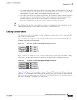
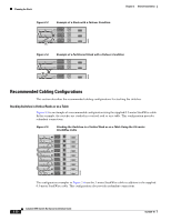
Planning the Stack Chapter 2 Switch Installation When POST completes successfully, the System LED remains green. The RPS LED remains green for some time and then returns to its operating status. The other LEDs turn off and return to their operating status. When POST fails, the System LED turns amber. Note POST failures are usually fatal. Call Cisco Systems if your switch does not pass POST. Powering Off the Switch After a successful POST, disconnect the power cord from the switch. Install the switch in a rack, on a wall, on a table, or on a shelf as described in the "Installing the Switch" section on page 2-11. Planning the Stack If you plan to stack your switches, read these sections: • Planning Considerations, page 2-8 • Powering Considerations, page 2-8 • Cabling Considerations, page 2-9 • Recommended Cabling Configurations, page 2-10 Planning Considerations Before connecting the Catalyst 3750 switches in a stack, observe these planning considerations: • Size of the switch. For switch dimensions, see Appendix A, "Technical Specifications." Some switches are deeper than the other switches. Stacking switches of the same size together makes it easier to cable the switches. • Length of cable. Depending on the configurations that you have, you might need cables of different sizes. If you do not specify the length of the StackWise cable, the 0.5-meter cable is supplied. If you require the 1-meter cable or the 3-meter cable, you can order it from your Cisco supplier. For cable numbers, see the "StackWise Ports" section on page 1-24. The "Recommended Cabling Configurations" section on page 2-10 provides examples of recommended configurations. • Access to the rear ports for unrestricted cabling. Make sure that you have access to the rear of the rack if you plan to stack the switches. If you do not have access to the rear panel, make sure that you cable the switches before you rack-mount them. • For concepts and procedures to manage switch stacks, see the switch software configuration guide. Powering Considerations Consider the following guidelines before you power on the switches in a stack: • The sequence in which you initially power on the switches might affect the switch that becomes the stack master. Catalyst 3750 Switch Hardware Installation Guide 2-8 OL-6336-10
-
 1
1 -
2
-
3
-
4
-
5
-
6
-
7
-
8
-
9
-
10
-
11
-
12
-
13
-
14
-
15
-
16
-
17
-
18
-
19
-
20
-
21
-
22
-
23
-
24
-
25
-
26
-
27
-
28
-
29
-
30
-
31
-
32
-
33
-
34
-
35
-
36
-
37
-
38
-
39
-
40
-
 41
41 -
 42
42 -
 43
43 -
 44
44 -
 45
45 -
 46
46 -
 47
47 -
 48
48 -
 49
49 -
 50
50 -
 51
51 -
52
-
53
-
54
-
55
-
56
-
57
-
58
-
59
-
60
-
61
-
62
-
63
-
64
-
65
-
66
-
67
-
68
-
69
-
70
-
71
-
72
-
73
-
74
-
75
-
76
-
77
-
78
-
79
-
80
-
81
-
82
-
83
-
84
-
85
-
86
-
87
-
88
-
89
-
90
-
91
-
92
-
93
-
94
-
95
-
96
-
97
-
98
-
99
-
100
-
101
-
102
-
103
-
104
-
105
-
106
-
107
-
108
-
109
-
110
-
111
-
112
-
113
-
114
-
115
-
116
-
117
-
118
-
119
-
120
-
121
-
122
-
123
-
124
-
125
-
126
-
127
-
128
-
129
-
130
-
131
-
132
-
133
-
134
-
135
-
136
-
137
-
138
-
139
-
140
-
141
-
142
-
143
-
144
-
145
-
146
 |
 |
