Cisco 3750G-12S Hardware Installation Guide - Page 47
Cabling Considerations, Example of a Stack with Full Bandwidth Connections
 |
UPC - 746320812526
View all Cisco 3750G-12S manuals
Add to My Manuals
Save this manual to your list of manuals |
Page 47 highlights
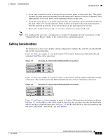
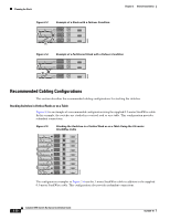
Chapter 2 Switch Installation Planning the Stack • If you want a particular switch to become the stack master, power on that switch first. This switch becomes the stack master and remains the stack master until a master re-election is required. After approximately 10 seconds, power on the remaining switches in the stack. • If you have no preference as to which switch becomes the stack master, power on all the switches in the stack within a 10-second timeframe. These switches participate in the stack master election. Switches powered up after the 10-second timeframe do not participate in the election. • Power off a switch before you add it to or remove it from an existing switch stack. Note For conditions that can cause a stack master re-election or to manually elect the stack master, see the "Managing Switch Stacks" chapter in the switch software configuration guide. Cabling Considerations The illustrations in this section display cabling configuration examples that show the stack bandwidth and possible stack partitioning. Figure 2-1 shows an example of a stack of Catalyst 3750 switches that provides full bandwidth and redundant StackWise cable connections. Figure 2-1 Example of a Stack with Full Bandwidth Connections 86821 A B C Figure 2-2 shows an example of a stack of Catalyst 3750 switches with incomplete StackWise cabling connections. This stack provides only half bandwidth and does not have redundant connections. Figure 2-2 Example of a Stack with Half Bandwidth Connections 86823 A B Figure 2-3 and Figure 2-4 show examples of stacks of Catalyst 3750 switches with failover conditions. In Figure 2-3, the StackWise cable is bad in link B; therefore, this stack provides only half bandwidth and does not have redundant connections. In Figure 2-4, link B is bad; therefore, this stack partitions into two stacks, and switch 1 and switch 3 are stack masters. OL-6336-10 Catalyst 3750 Switch Hardware Installation Guide 2-9
-
 1
1 -
2
-
3
-
4
-
5
-
6
-
7
-
8
-
9
-
10
-
11
-
12
-
13
-
14
-
15
-
16
-
17
-
18
-
19
-
20
-
21
-
22
-
23
-
24
-
25
-
26
-
27
-
28
-
29
-
30
-
31
-
32
-
33
-
34
-
35
-
36
-
37
-
38
-
39
-
40
-
41
-
 42
42 -
 43
43 -
 44
44 -
 45
45 -
 46
46 -
 47
47 -
 48
48 -
 49
49 -
 50
50 -
 51
51 -
 52
52 -
53
-
54
-
55
-
56
-
57
-
58
-
59
-
60
-
61
-
62
-
63
-
64
-
65
-
66
-
67
-
68
-
69
-
70
-
71
-
72
-
73
-
74
-
75
-
76
-
77
-
78
-
79
-
80
-
81
-
82
-
83
-
84
-
85
-
86
-
87
-
88
-
89
-
90
-
91
-
92
-
93
-
94
-
95
-
96
-
97
-
98
-
99
-
100
-
101
-
102
-
103
-
104
-
105
-
106
-
107
-
108
-
109
-
110
-
111
-
112
-
113
-
114
-
115
-
116
-
117
-
118
-
119
-
120
-
121
-
122
-
123
-
124
-
125
-
126
-
127
-
128
-
129
-
130
-
131
-
132
-
133
-
134
-
135
-
136
-
137
-
138
-
139
-
140
-
141
-
142
-
143
-
144
-
145
-
146
 |
 |
