Cisco ASR1006-10G-SEC/K9 Installation Guide - Page 19
Attaching a Chassis Ground Connection
 |
View all Cisco ASR1006-10G-SEC/K9 manuals
Add to My Manuals
Save this manual to your list of manuals |
Page 19 highlights
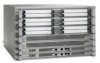
Chapter 6 Cisco ASR 1006 Router Overview and Installation Attaching a Chassis Ground Connection Figure 6-12 shows the cable-management bracket attached to the chassis in a rack. Figure 6-12 Installing the Cable-Management Bracket 1 STATUS A/L C/A A/L C/A A/L C/A STATUS STATUS STATUS 3 0 0 0 0 0 A/L C/A A/L C/A A/L C/A A/L C/A A/L C/A 1 1 1 1 1 A/L C/A A/L C/A A/L C/A A/L C/A A/L C/A 2 2 2 2 2 A/L C/A A/L C/A A/L C/A A/L C/A A/L C/A A/L C/A 3 3 3 3 3 A/L C/A A/L C/A A/L C/A A/L C/A A/L C/A A/L C/A SPA-4XOC3-POS SPA-4XOC3-POS SPA-4XOC3-POS SPA-4XOC3-POS SPA-4XOC3-POS SPA-4XOC3-POS STATUS STATUS STATUS STATUS STATUS STATUS 0 0 0 0 0 0 A/L C/A A/L C/A A/L C/A A/L C/A A/L C/A A/L C/A 1 1 1 1 1 1 A/L C/A A/L C/A A/L C/A A/L C/A A/L C/A 2 2 2 2 2 2 A/L C/A A/L C/A A/L C/A A/L C/A A/L C/A 3 3 3 3 3 3 A/L C/A A/L C/A A/L C/A A/L C/A A/L C/A SPA-4XOC3-POS SPA-4XOC3-POS SPA-4XOC3-POS SPA-4XOC3-POS SPA-4XOC3-POS SPA-4XOC3-POS STATUS STATUS A/L C/A 3 A/L C/A 2 1 0 280036 2 1 1 Cable-management bracket screw location 3 Chassis front rack-mount bracket and ear holes 2 Cable-management bracket -- This completes the procedure for installing the cable-management brackets on the chassis. Attaching a Chassis Ground Connection Connecting the Cisco ASR 1006 Router chassis to ground is required for all DC powered installations and any AC powered installation where compliance with Telcordia grounding requirements is necessary. Caution The dual-lug chassis stud must be installed, the SIP and SPA must be fully inserted and screwed in and earthed to prevent a potential hazard in a telecom line. OL-13208-09 Cisco ASR 1000 Series Aggregation Services Routers Hardware Installation Guide 6-19
-
 1
1 -
2
-
3
-
4
-
5
-
6
-
7
-
8
-
9
-
10
-
11
-
12
-
13
-
 14
14 -
 15
15 -
 16
16 -
 17
17 -
 18
18 -
 19
19 -
 20
20 -
 21
21 -
 22
22 -
 23
23 -
 24
24 -
25
-
26
-
27
-
28
-
29
-
30
-
31
-
32
-
33
-
34
-
35
-
36
 |
 |
