Cisco ASR1006-10G-SEC/K9 Installation Guide - Page 31
Cisco ASR 1006 Router DC Power Supply ASR1013/06-PWR-DC Terminal Block Ground Cable Lugs
 |
View all Cisco ASR1006-10G-SEC/K9 manuals
Add to My Manuals
Save this manual to your list of manuals |
Page 31 highlights
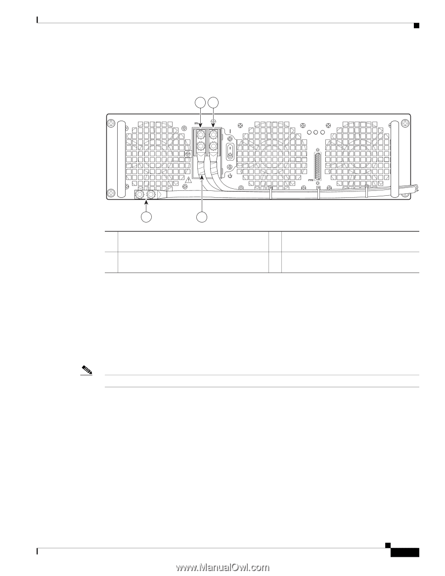
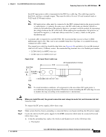
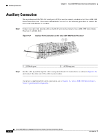
Chapter 6 Cisco ASR 1006 Router Overview and Installation Connecting Power to the Cisco ASR 1006 Router Figure 6-22 Figure 6-22 shows the ASR1013/06-PWR-DC power supply for the Cisco ASR 1006 Router. Cisco ASR 1006 Router DC Power Supply (ASR1013/06-PWR-DC) Terminal Block Ground Cable Lugs 12 -48/-60V 40A OUTPUT INPUT FAN FAIL OK OK 253913 ALARMS 60V 1A MAX This unit might have more than one power supply connection. All connections must be removed to de-energize the unit. 4 3 1 Negative lug and wire with sleeving wrapped around the wire and end of lug 2 Positive lug and wire with sleeving wrapped around the wire and end of lug 3 Location of sleeving wrapped around the wire and end of the grounding stud 4 Ground lug and wire Step 6 Step 7 For easier cable management, insert the negative lead cable first. Replace the ground lug with cable in the following order: a. Flat Washer b. Ground lug with negative wire c. Kepnut screw Tighten the Kepnut screw to recommended torque of 18 in-lbs minimum to 22 in-lbs maximum for the positive stud and wire. Note Secure the wires coming in from the terminal block so that they cannot be disturbed by casual contact. Step 8 Step 9 Use tie wraps to secure the wires, so that the wires are not pulled from the terminal block by casual contact. Ti-wrap studs are located below the power supply terminal block (see Figure 6-23). Replace the terminal block plastic cover and tighten the screw. The plastic cover is slotted and keyed to fit correctly over the terminal block. OL-13208-09 Cisco ASR 1000 Series Aggregation Services Routers Hardware Installation Guide 6-31
-
 1
1 -
2
-
3
-
4
-
5
-
6
-
7
-
8
-
9
-
10
-
11
-
12
-
13
-
14
-
15
-
16
-
17
-
18
-
19
-
20
-
21
-
22
-
23
-
24
-
25
-
 26
26 -
 27
27 -
 28
28 -
 29
29 -
 30
30 -
 31
31 -
 32
32 -
 33
33 -
 34
34 -
 35
35 -
 36
36
 |
 |