Cisco ASR1006-10G-SEC/K9 Installation Guide - Page 22
Connecting the Console and Auxiliary Port Cables, Connecting the Ethernet Management Port Cable
 |
View all Cisco ASR1006-10G-SEC/K9 manuals
Add to My Manuals
Save this manual to your list of manuals |
Page 22 highlights
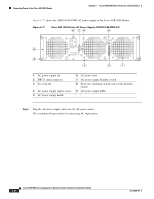
Connecting the Console and Auxiliary Port Cables Chapter 6 Cisco ASR 1006 Router Overview and Installation Shared port adapter documents are also available on the Cisco Documentation DVD. Connecting the Console and Auxiliary Port Cables The Cisco ASR 1006 Router has a DCE-mode console port for connecting a console terminal and a DTE-mode auxiliary port for connecting a modem or other DCE device (such as another router) to your chassis. Figure 6-15 shows the CON and AUX ports on the Cisco ASR 1000 Series route processor card. Figure 6-15 Cisco ASR 1000 Series Route Processor-CON and AUX Ports 12 3 A 2 A/L 1 A/L C/A 0 STATUS A/L C/A A/L C/A A/L C/A 3 A/L C/A SPA-4XOC3-POS SPA-4XOC3-POS STATUS 0 A/L C/A SPA-4XOC3-POS A/L C/A 2 A/L C/A 1 0 A/L C/A 3 A/L C/A 2 1 0 280181 CRIT PWR STAT ACTV MAJ STBY MIN ASR1000-RP1 ACO HD USB DF DISK 0 1 CARRIER LINK BITS MGMT ETHERNET AUX CON 1 CON connector 2 AUX connector Note Both the console and the auxiliary ports are asynchronous serial ports; any devices connected to these ports must be capable of asynchronous transmission. (Asynchronous is the most common type of serial device; for example, most modems are asynchronous devices.) The Cisco ASR 1006 Router uses RJ-45 ports for both the auxiliary port and the console port. For console and auxiliary port pinouts for the RJ-45 connector, see Appendix A, "Cisco ASR 1006 Router Specifications." Both ports are configured as asynchronous serial ports. Step 1 Step 2 Before connecting a terminal to the console port, configure the terminal to match the chassis console port as follows: 9600 baud, 8 data bits, no parity, 1 stop bits (9600 8N1). After you establish normal router operation, you can disconnect the terminal. Connecting the Ethernet Management Port Cable When using the Fast Ethernet Management port in the default mode (speed-auto and duplex-auto) the port operates in auto-MDI/MDI-X mode. The port automatically provides the correct signal connectivity through the Auto-MDI/MDI-X feature. The port automatically senses a crossover or straight-through cable and adapts to it. However, when the Fast Ethernet Management port is configured to a fixed speed (10 or 100 Mbps) through command-line interface (CLI) commands, the port is forced to MDI mode. 6-22 Cisco ASR 1000 Series Aggregation Services Routers Hardware Installation Guide OL-13208-09
-
 1
1 -
2
-
3
-
4
-
5
-
6
-
7
-
8
-
9
-
10
-
11
-
12
-
13
-
14
-
15
-
16
-
 17
17 -
 18
18 -
 19
19 -
 20
20 -
 21
21 -
 22
22 -
 23
23 -
 24
24 -
 25
25 -
 26
26 -
 27
27 -
28
-
29
-
30
-
31
-
32
-
33
-
34
-
35
-
36
 |
 |
