Cisco ASR1006-10G-SEC/K9 Installation Guide - Page 8
Equipment Shelf or Tabletop Installation
 |
View all Cisco ASR1006-10G-SEC/K9 manuals
Add to My Manuals
Save this manual to your list of manuals |
Page 8 highlights
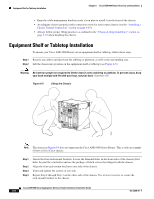
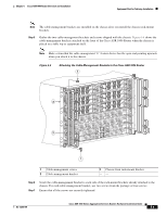
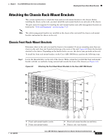
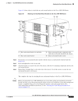
Equipment Shelf or Tabletop Installation Chapter 6 Cisco ASR 1006 Router Overview and Installation • Keep the cable-management brackets ready if you plan to install it on the front of the chassis. • An adequate chassis ground (earth) connection exists for your router chassis (see the "Attaching a Chassis Ground Connection" section on page 6-19). • Always follow proper lifting practices as outlined in the "Chassis-Lifting Guidelines" section on page 5-23 when handling the chassis. Equipment Shelf or Tabletop Installation To mount your Cisco ASR 1006 Router on an equipment shelf or tabletop, follow these steps. Step 1 Remove any debris and dust from the tabletop or platform, as well as the surrounding area. Step 2 Lift the chassis into position on the equipment shelf or tabletop (see Figure 6-5). Warning At least two people are required to lift the chassis onto a tabletop or platform. To prevent injury, keep your back straight and lift with your legs, not your back. Statement 164 Figure 6-5 Lifting the Chassis POWER FAULT MISWIRE POWER FAULT MISWIRE RX TX CARRIER LOOP ALARM CARRIER RX TX LINK FANS OK FAN FAILURE MULTIFAN FAILURE WrbseyemhsdetoeonvmnahelsoaihtnnCusduwtAdnarUodepwTeppnIrliaOntcwwgNeioltmlhmoiescnincftauumntre.utsrsaotyr, 1 CISCO 10000 2 CISCO 10000 3 CISCO 10000 4 CISCO 10000 FAIL FAIL FAIL FAIL LOOP CARALRAIERRM LOOP CARALRAIERRM 0 0 1 1 2 2 SSLLOOTT01 SSLLOOTT01 0A PROCESSOR ONLY0B CISCO 10000 CISCO 10000 CONSOLE AUX ELAICTNHTKIEVRITNYET CONSOLE AUX ELAICTNHTKIEVRITNYET LOOP CARALRAIERRM LOOP CARALRAIERRM LOOP CARALRAIERRM FAIL FAIL FAIL 5 CISCO 10000 0 6 CISCO 10000 0 7 CISCO 10000 0 1 1 1 3 3 2 2 2 4 4 5 5 3 3 3 4 4 4 5 5 5 FAIL 8 CISCO 10000 ACO CMRAIJTOICRAL MINOR SFATAILTUS ACO CMRAIJTOICRAL MINOR SFATAILTUS PROCESSOR ONLY OC-12/STM-4 POS SM-IR 6XCT3-DS0 6XCT3-DS0 6XCT3-DS0 PERFORMANCE ROUTING ENGINE PERFORMANCE ROUTING ENGINE 6XCT3-DS0 6XCT3-DS0 CH OC-12-DSO SM-IR GIGABIT ETHERNET 30007 Note The chassis in Figure 6-5 does not represent the Cisco ASR 1000 Series Router. This is only an example of how to lift a Cisco chassis. Step 1 Step 2 Step 3 Step 4 Attach the front rack-mount brackets. Locate the threaded holes in the front sides of the chassis (first holes beyond the vent holes) and use the package of black screws that shipped with the chassis. Align the front rack-mount bracket to one side of the chassis. Insert and tighten the screws on one side. Repeat Step 2 through Step 3 on the other side of the chassis. Use at least 4 screws to secure the rack-mount brackets to the chassis. Cisco ASR 1000 Series Aggregation Services Routers Hardware Installation Guide 6-8 OL-13208-09
-
 1
1 -
2
-
 3
3 -
 4
4 -
 5
5 -
 6
6 -
 7
7 -
 8
8 -
 9
9 -
 10
10 -
 11
11 -
 12
12 -
 13
13 -
14
-
15
-
16
-
17
-
18
-
19
-
20
-
21
-
22
-
23
-
24
-
25
-
26
-
27
-
28
-
29
-
30
-
31
-
32
-
33
-
34
-
35
-
36
 |
 |
