Cisco ASR1006-10G-SEC/K9 Installation Guide - Page 35
Connecting the System Cables
 |
View all Cisco ASR1006-10G-SEC/K9 manuals
Add to My Manuals
Save this manual to your list of manuals |
Page 35 highlights
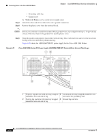
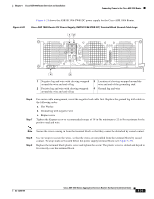
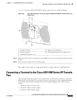
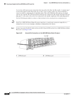
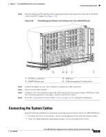
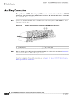
Chapter 6 Cisco ASR 1006 Router Overview and Installation Connecting the System Cables Step 2 Run the cable up and through the cable-management bracket and connect the other end of the RJ-45 cable to the RJ-45 adapter (see Figure 6-26). Figure 6-26 Cable-Management Bracket with Cabling in the Cisco ASR 1006 Router STATUS A/L C/A A/L C/A A/L C/A STATUS A/L C/A A/L C/A A/L C/A 3 A/L C/A STATUS A/L C/A 2 A/L C/A 1 A/L C/A 0 3 A/L C/A 2 STATUS 1 0 A/L C/A A/L C/A SPA-4XOC3-POS SPA-4XOC3-POS SPA-4XOC3-POS SPA-4XOC3-POS SPA-4XOC3-POS SPA-4XOC3-POS STATUS STATUS STATUS STATUS STATUS STATUS 0 0 0 0 0 0 A/L C/A A/L C/A A/L C/A A/L C/A A/L C/A A/L C/A 1 1 1 1 1 1 A/L C/A A/L C/A A/L C/A A/L C/A A/L C/A 2 2 2 2 2 2 A/L C/A A/L C/A A/L C/A A/L C/A A/L C/A 3 3 3 3 3 3 A/L C/A A/L C/A A/L C/A A/L C/A A/L C/A SPA-4XOC3-POS SPA-4XOC3-POS SPA-4XOC3-POS SPA-4XOC3-POS SPA-4XOC3-POS SPA-4XOC3-POS A/L C/A 3 A/L C/A STATUS A/L C/A 2 A/L C/A 1 A/L C/A 0 3 A/L C/A STATUS 2 1 A/L C/A 0 A/L C/A A/L C/A 3 A/L C/A A/L C/A 2 A/L C/A 1 0 A/L C/A 3 A/L C/A 2 1 0 280086 4 32 1 1 AUXiliary connection 2 MGMT Ethernet port 3 BITS port 4 Cable-management U feature device Step 3 Step 4 Step 5 Step 6 Connect the adapter to your video terminal to complete the cable connection. Power on your video terminal. Configure your video terminal to match the following default console port settings: 9600 baud, 8 data bits, No parity generation or checking, 1 stop bit, and No flow control. Go to the "Connecting the System Cables" section on page 6-35 to continue the installation. Connecting the System Cables Keep the following guidelines in mind when connecting external cables to the Cisco ASR 1006 Router: • To reduce the chance of interference, avoid crossing high-power lines with any interface cables. • Verify all cabling limitations (particularly distance) before powering on the system. OL-13208-09 Cisco ASR 1000 Series Aggregation Services Routers Hardware Installation Guide 6-35
-
 1
1 -
2
-
3
-
4
-
5
-
6
-
7
-
8
-
9
-
10
-
11
-
12
-
13
-
14
-
15
-
16
-
17
-
18
-
19
-
20
-
21
-
22
-
23
-
24
-
25
-
26
-
27
-
28
-
29
-
 30
30 -
 31
31 -
 32
32 -
 33
33 -
 34
34 -
 35
35 -
 36
36
 |
 |
