Cisco ASR1006-10G-SEC/K9 Installation Guide - Page 28
Cisco ASR 1006 Router -48, VDC Power Supply ASR1013/06-PWR-DC
 |
View all Cisco ASR1006-10G-SEC/K9 manuals
Add to My Manuals
Save this manual to your list of manuals |
Page 28 highlights
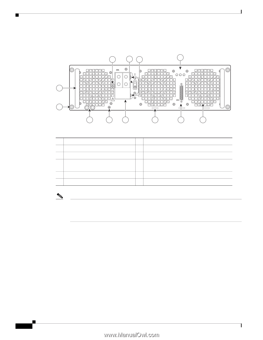
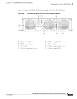
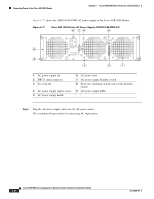
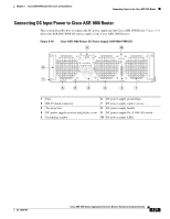
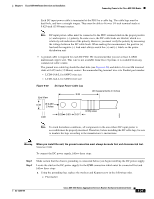
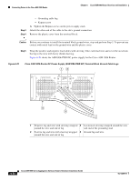
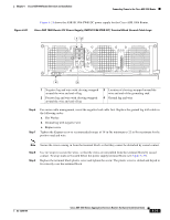
Connecting Power to the Cisco ASR 1006 Router Chapter 6 Cisco ASR 1006 Router Overview and Installation Figure 6-19 shows the ASR1013/06-PWR-DC power supply of the Cisco ASR 1006 Router. Figure 6-19 Cisco ASR 1006 Router -48 VDC Power Supply (ASR1013/06-PWR-DC) 9 10 11 12 -48/-60V 40A 8 OUTPUT INPUT FAN FAIL OK OK ALARMS 60V 1A MAX 7 This unit might have more than one power supply connection. All connections must be removed to de-energize the unit. 6 5 4 3 2 1 253912 1 Fan 7 DC power supply captive screw 2 DB-25 alarm connector 8 DC power supply handle 3 Tie-wrap tab 9 Terminal block and plastic cover single screw 4 DC power supply terminal block and 10 On/Off (|/O) circuit breaker switch plastic cover 5 Ground symbol 11 Terminal block and plastic cover slot tab 6 DC power supply ground studs 12 Power supply LEDs Note Shielded cables must be used to connect to the DB-25 alarm connector on both the AC and DC power supplies in order to comply with the FCC/EN55022/CISPR22 Class A emissions requirements. See the "How Cisco ASR1000-RP Alarm Monitoring Works" section on page 2-21. Before you begin the procedure to connect DC input power, read these important notices: • The color coding of the DC input power supply leads depends on the color coding of the DC power source at your site. Typically, green or green/yellow is used for ground (GND), black is used for -48 V on negative (-) terminal, and red is used for RTN on the positive (+) terminal. Make certain the lead color coding you choose for the DC input power supply matches the lead color coding used at the DC power source. • For DC input power cables, select the appropriate wire gauge based on the National Electrical Code (NEC) and local codes for 40-amp service at nominal DC input voltage (-48/-60 VDC). Three pairs of cable leads, source DC (-) and source DC return (+), are required for each power distribution unit (PDU). These cables are available from any commercial cable vendor. All input power cables for the chassis should have the same wire gauge and cable lengths should match within 10 percent of deviation. 6-28 Cisco ASR 1000 Series Aggregation Services Routers Hardware Installation Guide OL-13208-09
-
 1
1 -
2
-
3
-
4
-
5
-
6
-
7
-
8
-
9
-
10
-
11
-
12
-
13
-
14
-
15
-
16
-
17
-
18
-
19
-
20
-
21
-
22
-
 23
23 -
 24
24 -
 25
25 -
 26
26 -
 27
27 -
 28
28 -
 29
29 -
 30
30 -
 31
31 -
 32
32 -
 33
33 -
34
-
35
-
36
 |
 |