Cisco ASR1006-10G-SEC/K9 Installation Guide - Page 20
Recommended Tools and Supplies
 |
View all Cisco ASR1006-10G-SEC/K9 manuals
Add to My Manuals
Save this manual to your list of manuals |
Page 20 highlights
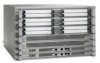
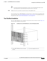
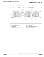
Attaching a Chassis Ground Connection Chapter 6 Cisco ASR 1006 Router Overview and Installation Have the recommended tools and supplies available before you begin this procedure. Figure 6-13 shows how to attach the ground lugs on the Cisco ASR 1006 chassis. Figure 6-13 Installing the Cisco ASR 1006 Router Ground Connection 4 3 280034 2 1 1 Chassis ground studs and lead wire 2 Grounding screws 3 Ground connector on the chassis 4 Ground symbol Warning This equipment must be grounded. Never defeat the ground conductor or operate the equipment in the absence of a suitably installed ground conductor. Contact the appropriate electrical inspection authority or an electrician if you are uncertain that suitable grounding is available. Statement 1024 Before you connect power or turn on power to your chassis, you must provide an adequate chassis ground (earth) connection for the chassis. A chassis ground connector is provided on each Cisco ASR 1006 Router. There is a stud on the side of the chassis and on the DC power supply (primary grounding stud). Caution The grounding wire is always the first to be installed or connected and the last to be removed or disconnected. Recommended Tools and Supplies The following tools, equipment, and supplies necessary to connect the system ground to the chassis: • Phillips screwdriver • Dual-lug chassis ground component • Grounding wire 6-20 Cisco ASR 1000 Series Aggregation Services Routers Hardware Installation Guide OL-13208-09
-
 1
1 -
2
-
3
-
4
-
5
-
6
-
7
-
8
-
9
-
10
-
11
-
12
-
13
-
14
-
 15
15 -
 16
16 -
 17
17 -
 18
18 -
 19
19 -
 20
20 -
 21
21 -
 22
22 -
 23
23 -
 24
24 -
 25
25 -
26
-
27
-
28
-
29
-
30
-
31
-
32
-
33
-
34
-
35
-
36
 |
 |
