Cisco ASR1006-10G-SEC/K9 Installation Guide - Page 21
Connecting the Shared Port Adapter Cables
 |
View all Cisco ASR1006-10G-SEC/K9 manuals
Add to My Manuals
Save this manual to your list of manuals |
Page 21 highlights
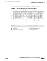
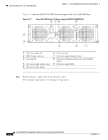
Chapter 6 Cisco ASR 1006 Router Overview and Installation Connecting the Shared Port Adapter Cables Use the following procedure to attach the grounding lug to the chassis ground connector on your chassis: Step 1 Step 2 Step 3 Step 4 Use the wire stripper to strip one end of the AWG #6 wire approximately 0.75 inches (19.05 mm). Insert the AWG #6 wire into the wire receptacle on the grounding lug. Use the crimping tool to carefully crimp the wire receptacle around the wire; this step is required to ensure a proper mechanical connection. Attach the grounding lug with the wire so that the grounding wire does not overlap the power supply (see Figure 6-14). Figure 6-14 Attaching a Grounding Lug to the Chassis Ground Connector 3 1 2 280186 4 1 Chassis ground lead wire 2 Grounding stud 3 Ground screws 4 Chassis ground connector holes Step 5 Step 6 Step 7 Step 8 Locate the chassis ground connector on the side of your chassis. Insert the two screws through the holes in the grounding lug. Use the Number 2 Phillips screwdriver to carefully tighten the screws until the grounding lug is held firmly to the chassis. Do not overtighten the screws. Connect the opposite end of the grounding wire to the appropriate grounding point at your site to ensure an adequate chassis ground. This completes the procedure for attaching a chassis ground connection. Go to the following cabling sections for information on attaching cables. Connecting the Shared Port Adapter Cables The instructions for connecting the cables for the shared port adapter installed in the Cisco ASR 1006 Router are contained in the respective configuration documents for each port adapter. For example, if you are connecting the optical fiber cables for the PA-POS-OC3 port adapter, see PA-POS-OC3 Port Adapter Installation and Configuration at the following location: http://www.cisco.com/en/US/partner/docs/interfaces_modules/port_adapters/install_upgrade/pos/pa-po s-oc3_install_config/paposoc3.html OL-13208-09 Cisco ASR 1000 Series Aggregation Services Routers Hardware Installation Guide 6-21
-
 1
1 -
2
-
3
-
4
-
5
-
6
-
7
-
8
-
9
-
10
-
11
-
12
-
13
-
14
-
15
-
 16
16 -
 17
17 -
 18
18 -
 19
19 -
 20
20 -
 21
21 -
 22
22 -
 23
23 -
 24
24 -
 25
25 -
 26
26 -
27
-
28
-
29
-
30
-
31
-
32
-
33
-
34
-
35
-
36
 |
 |
