Cisco ASR1006-10G-SEC/K9 Installation Guide - Page 25
Cisco ASR 1006 Router AC Power Supply ASR1006-PWR-AC
 |
View all Cisco ASR1006-10G-SEC/K9 manuals
Add to My Manuals
Save this manual to your list of manuals |
Page 25 highlights
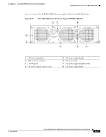
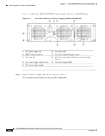
Chapter 6 Cisco ASR 1006 Router Overview and Installation Connecting Power to the Cisco ASR 1006 Router Figure 6-16 shows the ASR1006-PWR-AC power supply of the Cisco ASR 1006 Router. Figure 6-16 Cisco ASR 1006 Router AC Power Supply (ASR1006-PWR-AC) 67 8 OUTPUT INPUT INPUT FAIL OK OK ALARMS 60V 1A MAX 100-240V~ 16-7A 5 50-60HZ This unit might have more than one power supply connection. All connections must be removed to de-energize the unit. 4 3 2 1 1 AC power supply fan 2 DB-25 alarm connector 3 Tie-wrap tab 4 AC power supply captive screw 5 AC power supply handle 6 AC power inlet 7 AC power supply Standby switch 8 AC power supply LEDs 280029 OL-13208-09 Cisco ASR 1000 Series Aggregation Services Routers Hardware Installation Guide 6-25
-
 1
1 -
2
-
3
-
4
-
5
-
6
-
7
-
8
-
9
-
10
-
11
-
12
-
13
-
14
-
15
-
16
-
17
-
18
-
19
-
 20
20 -
 21
21 -
 22
22 -
 23
23 -
 24
24 -
 25
25 -
 26
26 -
 27
27 -
 28
28 -
 29
29 -
 30
30 -
31
-
32
-
33
-
34
-
35
-
36
 |
 |

6-25
Cisco ASR 1000 Series Aggregation Services Routers Hardware Installation Guide
OL-13208-09
Chapter 6
Cisco ASR 1006 Router Overview and Installation
Connecting Power to the Cisco ASR 1006 Router
Figure 6-16
shows the ASR1006-PWR-AC power supply of the Cisco ASR 1006 Router.
Figure 6-16
Cisco ASR 1006 Router AC Power Supply (ASR1006-PWR-AC)
1
AC power supply fan
5
AC power supply handle
2
DB-25 alarm connector
6
AC power inlet
3
Tie-wrap tab
7
AC power supply Standby switch
4
AC power supply captive screw
8
AC power supply LEDs
280029
OUTPUT INPUT
INPUT
FAIL
OK
OK
ALARMS
60V
1A MAX
100-240V~ 16-7A
50-60HZ
This unit might have more than
one power supply connection.
All connections must be removed
to de-energize the unit.
2
1
3
4
5
6
7
8