Cisco ASR1006-10G-SEC/K9 Installation Guide - Page 36
Auxiliary Connection
 |
View all Cisco ASR1006-10G-SEC/K9 manuals
Add to My Manuals
Save this manual to your list of manuals |
Page 36 highlights
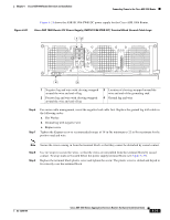
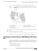
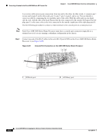
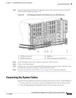
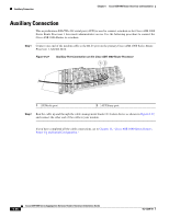
Auxiliary Connection Chapter 6 Cisco ASR 1006 Router Overview and Installation Auxiliary Connection This asynchronous EIA/TIA-232 serial port (AUX) is used to connect a modem to the Cisco ASR 1000 Series Route Processor 1 for remote administrative access. Use the following procedure to connect the Cisco ASR 1006 Router to a modem. Step 1 Connect one end of the modem cable to the RJ-45 port on the primary Cisco ASR 1000 Series Route Processor 1, labeled AUX. Figure 6-27 Auxiliary Port Connection on the Cisco ASR 1000 Route Processor 12 280094 CARRIER LINK MGMT ETHERNET BITS AUX CON CARRIER LINK MGMT ETHERNET BITS AUX CON 1 CONsole port 2 AUXiliary port Step 2 Run the cable up and through the cable-management bracket U feature device as shown in Figure 6-27, and connect the other end of the cable to your modem. If you have completed all the cable connections, go to Chapter 12, "Cisco ASR 1000 Series Routers Power Up and Initial Configuration." 6-36 Cisco ASR 1000 Series Aggregation Services Routers Hardware Installation Guide OL-13208-09
-
 1
1 -
2
-
3
-
4
-
5
-
6
-
7
-
8
-
9
-
10
-
11
-
12
-
13
-
14
-
15
-
16
-
17
-
18
-
19
-
20
-
21
-
22
-
23
-
24
-
25
-
26
-
27
-
28
-
29
-
30
-
 31
31 -
 32
32 -
 33
33 -
 34
34 -
 35
35 -
 36
36
 |
 |
