Cisco WS-C4003-RF Hardware Maintenance Manual - Page 31
Console Port and Auxiliary Port Connection Considerations, Console Port Connections
 |
View all Cisco WS-C4003-RF manuals
Add to My Manuals
Save this manual to your list of manuals |
Page 31 highlights
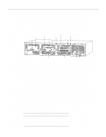
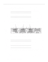
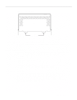
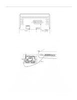
Figure 2-4 Slot Filler Panel Console Port and Auxiliary Port Connection Considerations Available Slot H1034a Alignment groove Mounting screw locations Alignment groove Console Port and Auxiliary Port Connection Considerations The following sections describe the console port and auxiliary port found on all Cisco 4000 series routers. Console Port Connections Each router includes an asynchronous router console port (female DB-25 connector) wired as a data communications equipment (DCE) device. The default parameters for this port follow: • 9600 baud • 8 data bits • No parity generated or checked • 2 stop bits In the appendix "Cabling Specifications," Table A-1 lists the pinout for the Cisco 4000-M console port and Table A-2 lists the pinout for the Cisco 4500-M and Cisco 4700 console port. Auxiliary Port Connections A male DB-25 connector auxiliary port (labeled AUX on the chassis rear) is included on all router units. The AUX port is a shared-memory data terminal equipment (DTE) port to which you can attach an EIA/TIA-232 connector from a channel service unit/data service unit (CSU/DSU), a modem, or protocol analyzer for network access. In the appendix "Cabling Specifications," Table A-1 lists the pinout for the Cisco 4000-M and Table A-2 lists the pinout for the Cisco 4500-M and Cisco 4700 asynchronous serial auxiliary port. Preparing for Installation 2-9
-
 1
1 -
2
-
3
-
4
-
5
-
6
-
7
-
8
-
9
-
10
-
11
-
12
-
13
-
14
-
15
-
16
-
17
-
18
-
19
-
20
-
21
-
22
-
23
-
24
-
25
-
 26
26 -
 27
27 -
 28
28 -
 29
29 -
 30
30 -
 31
31 -
 32
32 -
 33
33 -
 34
34 -
 35
35 -
 36
36 -
37
-
38
-
39
-
40
-
41
-
42
-
43
-
44
-
45
-
46
-
47
-
48
-
49
-
50
-
51
-
52
-
53
-
54
-
55
-
56
-
57
-
58
-
59
-
60
-
61
-
62
-
63
-
64
-
65
-
66
-
67
-
68
-
69
-
70
-
71
-
72
-
73
-
74
-
75
-
76
-
77
-
78
-
79
-
80
-
81
-
82
-
83
-
84
-
85
-
86
-
87
-
88
-
89
-
90
-
91
-
92
-
93
-
94
-
95
-
96
-
97
-
98
-
99
-
100
-
101
-
102
-
103
-
104
-
105
-
106
-
107
-
108
-
109
-
110
-
111
-
112
-
113
-
114
-
115
-
116
-
117
-
118
-
119
-
120
-
121
-
122
-
123
-
124
-
125
-
126
-
127
-
128
-
129
-
130
-
131
-
132
-
133
-
134
-
135
-
136
-
137
-
138
-
139
-
140
-
141
-
142
-
143
 |
 |
