Cisco WS-C4003-RF Hardware Maintenance Manual - Page 62
Making Serial Connections
 |
View all Cisco WS-C4003-RF manuals
Add to My Manuals
Save this manual to your list of manuals |
Page 62 highlights
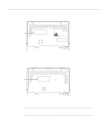
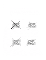
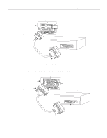
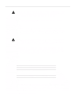
Making Network Connections Making Ethernet AUI Connections Follow these steps to make your AUI connections. Step 1 Attach the 15-pin D-type Ethernet port labeled AUI to the Ethernet AUI transition cable. (See Figure 2-7, Figure 2-8, and Figure 2-9 in the chapter "Preparing for Installation.") Step 2 Attach the slide-latch connector of the same cable to your transceiver or hub. Step 3 On a dual-port Ethernet network interface module, repeat Steps 1 and 2 for the second port. When all your network connections are complete, proceed to the section later in this chapter, "Making Final Connections to the Router." Making 10BaseT Connections Follow these steps to make your 10BaseT connections. Step 1 Attach the 10BaseT port labeled 10BaseT to the 10BaseT cable. (See Figure 2-5, Figure 2-6, and Figure 2-9 in the chapter "Preparing for Installation.") Step 2 Attach the other end of the 10BaseT cable to your network. Step 3 On a dual-port Ethernet network interface module, repeat steps 1 and 2 for the second port. When all your network connections are complete, proceed to the section later in this chapter, "Making Final Connections to the Router." Making Serial Connections The 60-pin DB-60 connector is standard on the four-port serial network processor module; the 50-pin DB-50 connector is standard on the dual serial network processor modules. Use the specific serial transition cable for the module type and the correct EIA/TIA standard connector for your modem or channel service unit/digital service unit (CSU/DSU) connector type. Caution The connector on the four-port serial module is upside down. The cable should match that orientation. Ensure that the 60-pin connectors on the cable and the network processor modules match. Do not force the cable into the connector upside down. (See Figure 3-4.) Figure 3-4 60-Pin Four-Port Serial Cable Connections Router Cable Correct H2324 Incorrect Follow these steps to make your serial connections. Step 1 Attach the ends of your serial transition cables to the synchronous serial ports of the serial network processor modules. (See Figure 3-5 and Figure 3-6.) Step 2 Attach the EIA/TIA-232, EIA/TIA-449, V.35, X.21, or EIA-530 end of the cable to the channel service unit/data service unit (CSU/DSU) or modem. 3-4 Cisco 4000 Series Hardware Installation and Maintenance
-
 1
1 -
2
-
3
-
4
-
5
-
6
-
7
-
8
-
9
-
10
-
11
-
12
-
13
-
14
-
15
-
16
-
17
-
18
-
19
-
20
-
21
-
22
-
23
-
24
-
25
-
26
-
27
-
28
-
29
-
30
-
31
-
32
-
33
-
34
-
35
-
36
-
37
-
38
-
39
-
40
-
41
-
42
-
43
-
44
-
45
-
46
-
47
-
48
-
49
-
50
-
51
-
52
-
53
-
54
-
55
-
56
-
 57
57 -
 58
58 -
 59
59 -
 60
60 -
 61
61 -
 62
62 -
 63
63 -
 64
64 -
 65
65 -
 66
66 -
 67
67 -
68
-
69
-
70
-
71
-
72
-
73
-
74
-
75
-
76
-
77
-
78
-
79
-
80
-
81
-
82
-
83
-
84
-
85
-
86
-
87
-
88
-
89
-
90
-
91
-
92
-
93
-
94
-
95
-
96
-
97
-
98
-
99
-
100
-
101
-
102
-
103
-
104
-
105
-
106
-
107
-
108
-
109
-
110
-
111
-
112
-
113
-
114
-
115
-
116
-
117
-
118
-
119
-
120
-
121
-
122
-
123
-
124
-
125
-
126
-
127
-
128
-
129
-
130
-
131
-
132
-
133
-
134
-
135
-
136
-
137
-
138
-
139
-
140
-
141
-
142
-
143
 |
 |
