Cisco WS-C4003-RF Hardware Maintenance Manual - Page 84
Reading Network Processor Module LED Indicators
 |
View all Cisco WS-C4003-RF manuals
Add to My Manuals
Save this manual to your list of manuals |
Page 84 highlights
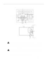
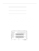
Reading Network Processor Module LED Indicators From left to right, when facing the chassis front, the three lower LEDs on the left correspond in position to the three network processor modules, if present, and represent their status. The upper LEDs, when blinking, indicate network activity on their respective interfaces. When on, the bottom LED on the far right indicates that the system card's power is on, and the top LED on the far right indicates that the processor is working. Reading Network Processor Module LED Indicators The network processor module LEDs are all visible through cutouts in the rear of the chassis. Ethernet Network Processor Module LED Indicators When facing the rear of the chassis, the LEDs on the dual-port Ethernet network processor module are labeled as shown in Figure 4-2. (Also see Figure 2-9.) Figure 4-2 TX RX AUI LNK POL Dual-Port Ethernet Network Processor Module LEDs H1568a TX RX AUI LNK POL When facing the rear of the chassis, the LEDs on the single-port Ethernet network processor module are labeled as shown in Figure 4-3. (Also see Figure 2-5.) Figure 4-3 Single-Port Ethernet Network Processor Module LEDs H1126a AUI POL LNK RX TX Descriptions of the Ethernet LED indicators follow: • AUI-When lit, this indicates the AUI connection is selected. Use the media command to configure your selection of 10BaseT or AUI. The syntax of the media command follows: media-type aui | 10BaseT Details on the media command are in the appropriate IOS software publication. When AUI is selected, none of the other LEDs on the network processor module will be lit. The other LEDs are meaningful only when you use 10BaseT, and you have a link. 4-4 Cisco 4000 Series Hardware Installation and Maintenance
-
 1
1 -
2
-
3
-
4
-
5
-
6
-
7
-
8
-
9
-
10
-
11
-
12
-
13
-
14
-
15
-
16
-
17
-
18
-
19
-
20
-
21
-
22
-
23
-
24
-
25
-
26
-
27
-
28
-
29
-
30
-
31
-
32
-
33
-
34
-
35
-
36
-
37
-
38
-
39
-
40
-
41
-
42
-
43
-
44
-
45
-
46
-
47
-
48
-
49
-
50
-
51
-
52
-
53
-
54
-
55
-
56
-
57
-
58
-
59
-
60
-
61
-
62
-
63
-
64
-
65
-
66
-
67
-
68
-
69
-
70
-
71
-
72
-
73
-
74
-
75
-
76
-
77
-
78
-
 79
79 -
 80
80 -
 81
81 -
 82
82 -
 83
83 -
 84
84 -
 85
85 -
 86
86 -
 87
87 -
 88
88 -
 89
89 -
90
-
91
-
92
-
93
-
94
-
95
-
96
-
97
-
98
-
99
-
100
-
101
-
102
-
103
-
104
-
105
-
106
-
107
-
108
-
109
-
110
-
111
-
112
-
113
-
114
-
115
-
116
-
117
-
118
-
119
-
120
-
121
-
122
-
123
-
124
-
125
-
126
-
127
-
128
-
129
-
130
-
131
-
132
-
133
-
134
-
135
-
136
-
137
-
138
-
139
-
140
-
141
-
142
-
143
 |
 |
