Cisco WS-C4003-RF Hardware Maintenance Manual - Page 53
T1 Cabling, cT1 / PRI
 |
View all Cisco WS-C4003-RF manuals
Add to My Manuals
Save this manual to your list of manuals |
Page 53 highlights
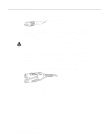
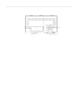
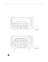
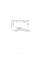
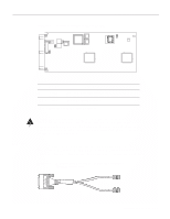
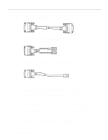
Network Connection Considerations Figure 2-32 Channelized T1 Network Interface Processor cT1 / PRI LOOPBACK LOCAL ALARM REMOTE ALARM H3155 DB-15 female T1 Cabling Following are the T1 specifications: • Transmission bit rate: 1.544 megabits per second (Mbps) ± 50 parts per million (ppm) • Output pulse amplitude: 3.0 volts (V) ± 0.6V measured at DSX • Output pulse width: 324 nanoseconds (ns) ± 54 ns • Complies with all AT&T Accunet TR 62411 specifications For the CT1, two standard T1 serial cables are available from Cisco Systems: null-modem and straight-through. A straight through cable connects your router to an external CSU. Null modem cables are used for back-to-back operation and testing. The cables have male 15-pin DB connectors at each end to connect the CT1with the external CSU. The T1 interface cable has two 15-pin DB connectors at each end to connect the CT1with the external T1 CSU. Figure 2-33 shows the T1 interface cable, connectors and pin-outs. Figure 2-33 T1 Interface Cable in 1 in 9 Pin 3 Pin 11 72-XXXX-01 MIP in 11 in 3 T1 or null-modem connector (typical) Pin 9 Pin 1 H2385 Preparing for Installation 2-31
-
 1
1 -
2
-
3
-
4
-
5
-
6
-
7
-
8
-
9
-
10
-
11
-
12
-
13
-
14
-
15
-
16
-
17
-
18
-
19
-
20
-
21
-
22
-
23
-
24
-
25
-
26
-
27
-
28
-
29
-
30
-
31
-
32
-
33
-
34
-
35
-
36
-
37
-
38
-
39
-
40
-
41
-
42
-
43
-
44
-
45
-
46
-
47
-
 48
48 -
 49
49 -
 50
50 -
 51
51 -
 52
52 -
 53
53 -
 54
54 -
 55
55 -
 56
56 -
 57
57 -
 58
58 -
59
-
60
-
61
-
62
-
63
-
64
-
65
-
66
-
67
-
68
-
69
-
70
-
71
-
72
-
73
-
74
-
75
-
76
-
77
-
78
-
79
-
80
-
81
-
82
-
83
-
84
-
85
-
86
-
87
-
88
-
89
-
90
-
91
-
92
-
93
-
94
-
95
-
96
-
97
-
98
-
99
-
100
-
101
-
102
-
103
-
104
-
105
-
106
-
107
-
108
-
109
-
110
-
111
-
112
-
113
-
114
-
115
-
116
-
117
-
118
-
119
-
120
-
121
-
122
-
123
-
124
-
125
-
126
-
127
-
128
-
129
-
130
-
131
-
132
-
133
-
134
-
135
-
136
-
137
-
138
-
139
-
140
-
141
-
142
-
143
 |
 |
