Cisco WS-C4003-RF Hardware Maintenance Manual - Page 66
BRI Interface Port Pinout, Testing the BRI Interface, BRI Network Processor Module LED Indications
 |
View all Cisco WS-C4003-RF manuals
Add to My Manuals
Save this manual to your list of manuals |
Page 66 highlights
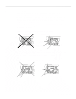
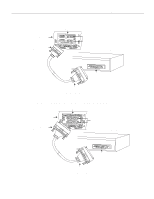
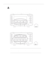
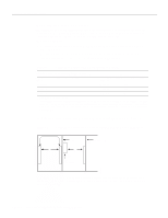
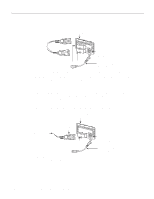
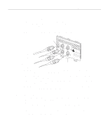
Making Network Connections BRI Interface Port Pinout The BRI interface port pinout is shown in Table 3-2. Table 3-2 BRI Port Pinout (RJ-45) 8 Pin1 TE2 NT3 Polarity 3 Transmit Receive + 4 Receive Transmit + 5 Receive Transmit - 6 Transmit Receive - 1. Pins 1, 2, 7, and 8 are not used. 2. TE refers to terminal terminating layer 1 aspects of TE1, TA, and NT2 functional groups. 3. NT refers to network terminating layer 1 aspects of NT1 and NT2 functional groups. Caution To prevent damage to the system, make certain you connect the BRI cable to the BRI connector only and not to any other RJ-45 connector. Testing the BRI Interface An external loopback RJ-45 connector, useful for isolating hardware problems on an individual BRI port, can be constructed as follows: Step 1 Connect Pin 3 to Pin 4. (See Figure 3-7 and Figure 3-8.) Step 2 Connect Pin 5 to Pin 6. Step 3 Connect a 50-ohm resistor across Pin 3 and Pin 5. Note Pins 1, 2, 7, and 8 are not connected. With the loopback RJ-45 connector plug installed in a BRI port, use the test interface command to determine that the hardware is functioning correctly. BRI Network Processor Module LED Indications When on, the multiport BRI network processor module status LEDs indicate a Layer 1 connection on the corresponding port. When not on, the LEDs indicate that the link is not established on the corresponding port. BRI Network Processor Module Independent of Host The Cisco Systems Basic Rate Interface (BRI) network processor module is a processor/interface card assembly for use within a range of data communication (gateway and router) chassis supplied by Cisco Systems throughout Europe. The BRI module is a self-contained product that provides all of the hardware necessary to allow connection of Cisco Systems' chassis to either four or eight Basic Access Integrated Switched Digital Networks (ISDN), each at the S reference point. The ISDN usage is restricted to the point-to-point mode only. 3-8 Cisco 4000 Series Hardware Installation and Maintenance
-
 1
1 -
2
-
3
-
4
-
5
-
6
-
7
-
8
-
9
-
10
-
11
-
12
-
13
-
14
-
15
-
16
-
17
-
18
-
19
-
20
-
21
-
22
-
23
-
24
-
25
-
26
-
27
-
28
-
29
-
30
-
31
-
32
-
33
-
34
-
35
-
36
-
37
-
38
-
39
-
40
-
41
-
42
-
43
-
44
-
45
-
46
-
47
-
48
-
49
-
50
-
51
-
52
-
53
-
54
-
55
-
56
-
57
-
58
-
59
-
60
-
 61
61 -
 62
62 -
 63
63 -
 64
64 -
 65
65 -
 66
66 -
 67
67 -
 68
68 -
 69
69 -
 70
70 -
 71
71 -
72
-
73
-
74
-
75
-
76
-
77
-
78
-
79
-
80
-
81
-
82
-
83
-
84
-
85
-
86
-
87
-
88
-
89
-
90
-
91
-
92
-
93
-
94
-
95
-
96
-
97
-
98
-
99
-
100
-
101
-
102
-
103
-
104
-
105
-
106
-
107
-
108
-
109
-
110
-
111
-
112
-
113
-
114
-
115
-
116
-
117
-
118
-
119
-
120
-
121
-
122
-
123
-
124
-
125
-
126
-
127
-
128
-
129
-
130
-
131
-
132
-
133
-
134
-
135
-
136
-
137
-
138
-
139
-
140
-
141
-
142
-
143
 |
 |
