Cisco WS-C4003-RF Hardware Maintenance Manual - Page 34
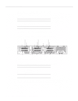
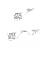
Dual-Port Ethernet Module Connections, Slide-latch, connector, transition cable, Router, rear view
 |
View all Cisco WS-C4003-RF manuals
Add to My Manuals
Save this manual to your list of manuals |
Page 34 highlights
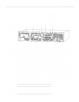
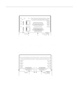
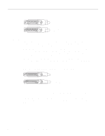
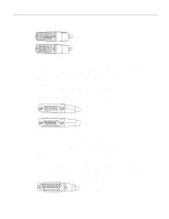
Network Connection Considerations Router (rear view) Figure 2-7 Single-Port Ethernet Network Processor Module AUI Port Connection Ethernet module Transceiver Slide-latch connector H1525a AUI Router (rear view) AUX 18" transition cable Figure 2-8 shows the transition cable used as a flexible extension of the Ethernet port allowing an Ethernet transceiver cable with a slide-latch connector to mate with the female end of the 18-inch transition cable. Figure 2-8 Extending the Transition Cable from the Ethernet Port Ethernet module Slide-latch connector Slide-latch connector Ethernet (AUI) transceiver H1526a AUI AUX 18" transition cable Dual-Port Ethernet Module Connections The dual-port Ethernet network processor module has ports for two network connections. (See Figure 2-9.) The top port is marked Port-1 on the module, and the lower port is marked Port-0. On the dual-port Ethernet network processor module, on a given port, either the Ethernet connector or the 10BaseT connector can be used, but not both. For example, Ethernet port 0 could be attached to either a 10BaseT connector or to an AUI connector, and similarly Ethernet port 1 could be attached to either a 10BaseT connector or to an AUI connector. 2-12 Cisco 4000 Series Hardware Installation and Maintenance
-
 1
1 -
2
-
3
-
4
-
5
-
6
-
7
-
8
-
9
-
10
-
11
-
12
-
13
-
14
-
15
-
16
-
17
-
18
-
19
-
20
-
21
-
22
-
23
-
24
-
25
-
26
-
27
-
28
-
 29
29 -
 30
30 -
 31
31 -
 32
32 -
 33
33 -
 34
34 -
 35
35 -
 36
36 -
 37
37 -
 38
38 -
 39
39 -
40
-
41
-
42
-
43
-
44
-
45
-
46
-
47
-
48
-
49
-
50
-
51
-
52
-
53
-
54
-
55
-
56
-
57
-
58
-
59
-
60
-
61
-
62
-
63
-
64
-
65
-
66
-
67
-
68
-
69
-
70
-
71
-
72
-
73
-
74
-
75
-
76
-
77
-
78
-
79
-
80
-
81
-
82
-
83
-
84
-
85
-
86
-
87
-
88
-
89
-
90
-
91
-
92
-
93
-
94
-
95
-
96
-
97
-
98
-
99
-
100
-
101
-
102
-
103
-
104
-
105
-
106
-
107
-
108
-
109
-
110
-
111
-
112
-
113
-
114
-
115
-
116
-
117
-
118
-
119
-
120
-
121
-
122
-
123
-
124
-
125
-
126
-
127
-
128
-
129
-
130
-
131
-
132
-
133
-
134
-
135
-
136
-
137
-
138
-
139
-
140
-
141
-
142
-
143
 |
 |
