Cisco WS-C4003-RF Hardware Maintenance Manual - Page 79
Connecting Routers with a DC-Input Power Supply, DC-Input Power Supply Connections
 |
View all Cisco WS-C4003-RF manuals
Add to My Manuals
Save this manual to your list of manuals |
Page 79 highlights
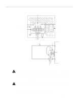
Connecting Routers with a DC-Input Power Supply Figure 3-15 DC-Input Power Supply Connections Negative Ground Terminal block cover Terminal block Positive On/Off Captive screw Grommet Terminal block cover Terminal block H2275 Grommet Warning After wiring the DC-input power supply, replace the terminal block cover and screw to ensure user safety. Step 4 Remove the tape from the circuit breaker switch handle and restore power by moving the circuit breaker handle to the ON position. Caution To avoid damaging the power supply when returning the chassis to the manufacturer (for example, if a failure occurs), remove the power supply terminal block cover so that it will fit in the shipping container. This completes the procedure for wiring the DC-input power supply. Installing the Router 3-21
-
 1
1 -
2
-
3
-
4
-
5
-
6
-
7
-
8
-
9
-
10
-
11
-
12
-
13
-
14
-
15
-
16
-
17
-
18
-
19
-
20
-
21
-
22
-
23
-
24
-
25
-
26
-
27
-
28
-
29
-
30
-
31
-
32
-
33
-
34
-
35
-
36
-
37
-
38
-
39
-
40
-
41
-
42
-
43
-
44
-
45
-
46
-
47
-
48
-
49
-
50
-
51
-
52
-
53
-
54
-
55
-
56
-
57
-
58
-
59
-
60
-
61
-
62
-
63
-
64
-
65
-
66
-
67
-
68
-
69
-
70
-
71
-
72
-
73
-
 74
74 -
 75
75 -
 76
76 -
 77
77 -
 78
78 -
 79
79 -
 80
80 -
 81
81 -
 82
82 -
 83
83 -
 84
84 -
85
-
86
-
87
-
88
-
89
-
90
-
91
-
92
-
93
-
94
-
95
-
96
-
97
-
98
-
99
-
100
-
101
-
102
-
103
-
104
-
105
-
106
-
107
-
108
-
109
-
110
-
111
-
112
-
113
-
114
-
115
-
116
-
117
-
118
-
119
-
120
-
121
-
122
-
123
-
124
-
125
-
126
-
127
-
128
-
129
-
130
-
131
-
132
-
133
-
134
-
135
-
136
-
137
-
138
-
139
-
140
-
141
-
142
-
143
 |
 |
