D-Link DSN-4200 Hardware Reference Guide for DSN-4000
D-Link DSN-4200 Manual
 |
View all D-Link DSN-4200 manuals
Add to My Manuals
Save this manual to your list of manuals |
D-Link DSN-4200 manual content summary:
- D-Link DSN-4200 | Hardware Reference Guide for DSN-4000 - Page 1
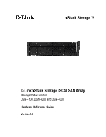
xStack Storage TM D-Link xStack Storage iSCSI SAN Array Managed SAN Solution DSN-4100, DSN-4200 and DSN-4000 Hardware Reference Guide Version 1.0 - D-Link DSN-4200 | Hardware Reference Guide for DSN-4000 - Page 2
ii - D-Link DSN-4200 | Hardware Reference Guide for DSN-4000 - Page 3
or service marks, and are used to identify products or services, of DLink is not responsible for any loss of data resulting from the use, disuse or misuse of this or any other D-Link product. Notice and Recommendations Although D-Link has attempted to ensure the accuracy of the content of this manual - D-Link DSN-4200 | Hardware Reference Guide for DSN-4000 - Page 4
, should you need to replace it, please consult your service documentation. There is a danger of a new battery exploding DISPOSE OF USED BATTERIES ACCORDING TO THE INSTRUCTIONS. Notice of Export Controls Export of United States government. Please contact D-Link, Inc. for any export compliance - D-Link DSN-4200 | Hardware Reference Guide for DSN-4000 - Page 5
Documentation In addition to this document, the following documents are available from D-Link. xStack Storage Management Center Software User's Guide. This guide provides the information needed to configure and manage storage on the xStack Storage system using the xStack graphical user interface - D-Link DSN-4200 | Hardware Reference Guide for DSN-4000 - Page 6
to Friday 8:00am - 5:00pm PST/PDT D-Link Technical Support over the Internet: • http://support.dlink.com Tech Support for customers within Canada: D-Link Technical Support over the Telephone Please see our support site for current number: • http://support.dlink.ca • Monday to Friday 7:30am to 9:00pm - D-Link DSN-4200 | Hardware Reference Guide for DSN-4000 - Page 7
Ports 16 3.7 Connecting to the Management Port 16 3.8 Connecting the AC Power Cords 18 3.9 Connect any DSN-4000 JBOD Expansion Arrays (optional 18 3.10 Powering-on the DSN the Diagnostic Serial Port 27 Appendix B Installing the System in a Rack 29 DSN-4000 Series Hardware Reference Guide vii - D-Link DSN-4200 | Hardware Reference Guide for DSN-4000 - Page 8
This page intentionally left blank. viii Contents - D-Link DSN-4200 | Hardware Reference Guide for DSN-4000 - Page 9
5mm RS-232-C stereo mini-jack diagnostic port for troubleshooting purposes Complete configuration and management of the storage system are available through the intuitive, graphical-based Management Center software. 1.1 Models The D-Link xStack Storage DSN-4000 series storage array is available in - D-Link DSN-4200 | Hardware Reference Guide for DSN-4000 - Page 10
access to critical information In-band or out-of-band management via direct connection or the Web Delivers Ethernet economics to storage used solely for exchanging data between the customer's host servers and the DSN-4000 series array. The Ethernet bandwidth used by the servers exchanging data with - D-Link DSN-4200 | Hardware Reference Guide for DSN-4000 - Page 11
Array Layout This chapter describes the hardware components on the DSN-4X00 primary array. The topics covered in this chapter are: Section 2.1, Front Panel Components Section 2.2, Rear Panel Components Section 2.3, Side, Top and Bottom Panel Components DSN-4000 Series Hardware Reference Guide 3 - D-Link DSN-4200 | Hardware Reference Guide for DSN-4000 - Page 12
components (see Figure 2-1): Enclosure Status LEDs - the enclosure LEDs at the right side of the front panel provide status information about the DSN-4X00i primary array enclosure, as shown in Figure 2-1. For a description of these LEDs, see Table 2-1. Drive Slots - the front panel provides access - D-Link DSN-4200 | Hardware Reference Guide for DSN-4000 - Page 13
disk is idle or no disk is present. Flashing Green: A hard disk is present and there is disk activity. Figure 2-4. Drive Slot Numbers on the DSN-4X00 Primary Array DSN-4000 Series Hardware Reference Guide 5 - D-Link DSN-4200 | Hardware Reference Guide for DSN-4000 - Page 14
The rear panel of the DSN-4X00 primary array has the following components (see Figure 2-5 through Figure 2-8): Management port (Mgmt) - one 10/100/1000 RJ-45 management is located to the left of the iSCSI data ports. The management port includes port speed and port activity LEDs. For more - D-Link DSN-4200 | Hardware Reference Guide for DSN-4000 - Page 15
-4200 Controller Module Ejection Lever Figure 2-7. Detailed View of 8-port DSN-4200 Controller Rear Panel Figure 2-8. Detailed View of 4-port DSN-4100 Controller Rear Panel Table 2-3. Management Port LEDs LED Port Activity Link Speed Description Flashing Amber: Data is being sent or received - D-Link DSN-4200 | Hardware Reference Guide for DSN-4000 - Page 16
2-4. 1-Gigabit iSCSI Data Port LEDs LED Port Activity Link Speed Description Flashing Green: Data is being sent or received Off: No data is being sent or received Green: Network link is operating at 1000 Mbps Amber: Network link is operating at 100 Mbps Off: No network link is detected Table - D-Link DSN-4200 | Hardware Reference Guide for DSN-4000 - Page 17
2.3 Side, Top and Bottom Panel Components The left and right sides of the DSN-4X00 enclosure do not require any special hardware for rack-mounting the unit. Instead . For rack-mount instructions, refer to Appendix B and the documentation for your rack. DSN-4000 Series Hardware Reference Guide 9 - D-Link DSN-4200 | Hardware Reference Guide for DSN-4000 - Page 18
This page intentionally left blank. 10 Chapter 2 VessRAID 1836i/1846i Series Primary Array Layout - D-Link DSN-4200 | Hardware Reference Guide for DSN-4000 - Page 19
to the Management Port Section 3.8, Connecting the AC Power Cords Section 3.9, Connect any DSN-4000 JBOD Expansion Arrays (optional) Section 3.10, Powering-on the DSN-4000 JBOD Expansion Arrays Section 3.11, Powering-on the DSN-4X00 Storage Array DSN-4000 Series Hardware Reference Guide 11 - D-Link DSN-4200 | Hardware Reference Guide for DSN-4000 - Page 20
or shelf installations. Select a sturdy, level surface that can support the DSN-4X00 storage array. A fully populated unit weighs approximately 35 1.1 pound / 0.5 kg per drive). Allow enough ventilation space between the DSN-4X00 storage array and any other objects in the vicinity. Be sure not - D-Link DSN-4200 | Hardware Reference Guide for DSN-4000 - Page 21
. Follow the instructions in the documentation for the rack. The operating ambient temperature of rack-mounted equipment must not exceed the maximum rated ambient temperature indicated in this guide. The rack cabinet must provide sufficient airflow to the front and back of the DSN-4X00 storage array - D-Link DSN-4200 | Hardware Reference Guide for DSN-4000 - Page 22
RJ-45 data port that will connect to your SAN (the primary array will auto-detect the network link speed and type of cable used). An Ethernet switch and Ethernet cables are optional. If you want to use the DSN-4X00 storage array's Link Aggregation feature, the network switch must support LAGs. SAS - D-Link DSN-4200 | Hardware Reference Guide for DSN-4000 - Page 23
SATA hard disk drives into your DSN-4X00 primary storage array and any DSN-4000 JBOD expansion arrays: Do drive. a. Install only the counter-sunk screws supplied with the DSN-4X00 system. b. Install four screws per drive (two on each with the DSN-4X00 system. Please verify that the drives you wish - D-Link DSN-4200 | Hardware Reference Guide for DSN-4000 - Page 24
1 using another Ethernet cable and the next available DSN-4X00 primary array port in sequence (port iSCSI-1, then port iSCSI-2, and so on). 3.7 Connecting to the Management Port Connecting a PC to the management port lets you configure and manage the DSN-4X00 storage array. This connection is made - D-Link DSN-4200 | Hardware Reference Guide for DSN-4000 - Page 25
Figure 3-2. Connecting the Data and Management Ports (8-port configuration shown) DSN-4000 Series Hardware Reference Guide 17 - D-Link DSN-4200 | Hardware Reference Guide for DSN-4000 - Page 26
labeled SAS EXP and ensure that it snaps fully into place. 2. To attach additional expansion arrays, use the expansion cable that was supplied with the DSN-4000 JBOD array between the SAS OUT connector (diamond icon) on one expansion array and the SAS IN connector (circle icon) on the next expansion - D-Link DSN-4200 | Hardware Reference Guide for DSN-4000 - Page 27
DSN-4000 JBOD expansion arrays. Only connect DSN-4000 JBOD Expansion Arrays to the DSN-4X00 storage system. No other commercially-available SAS expansion arrays are supported the unit. When the DSN-4000 JBOD expansion array hard disk turns green. The DSN-4000 JBOD expansion array runs its power - D-Link DSN-4200 | Hardware Reference Guide for DSN-4000 - Page 28
will be initialized automatically (unless they had been previously used in another D-Link array, in which case you will need to manually initialize those drives). To avoid possible loss of data, do not disconnect any of the DSN-4000 JBOD expansion arrays from the primary array while the system is - D-Link DSN-4200 | Hardware Reference Guide for DSN-4000 - Page 29
Appendix A Replacing and Upgrading FRUs This appendix describes how to replace the Field Replaceable Units (FRUs) in the DSN-4000 series arrays. FRUs that can be replaced or upgraded include: SATA and SAS Drives Power Supply Modules Cooling Fan Modules Controller Module Cache Battery - D-Link DSN-4200 | Hardware Reference Guide for DSN-4000 - Page 30
procedure: 1. Squeeze the latching mechanism on the front of the drive carrier that you wish to remove. 2. Pull the drive carrier out of the DSN-4000 series enclosure. Be careful to remove the correct drive carrier, since removing the wrong drive may cause some volumes to fail or become reduced. - D-Link DSN-4200 | Hardware Reference Guide for DSN-4000 - Page 31
power supplies on the DSN-4000 series are field- module. 5. Pull the power supply module out of the DSN-4000 series enclosure. Retaining Screw for Power Supply #0 Retaining : 1. Carefully slide the power supply module into the DSN-4000 series enclosure. 2. Install and tighten the retaining screw - D-Link DSN-4200 | Hardware Reference Guide for DSN-4000 - Page 32
A.3 Replacing a Cooling Fan Module The cooling fan modules on the DSN-4000 series are hot-swappable and can be replaced while the system is running, without shutting down the system or removing the enclosure from the - D-Link DSN-4200 | Hardware Reference Guide for DSN-4000 - Page 33
Primary Array The controller module monitors and manages the logical volumes and the iSCSI do so by D-Link Technical Support. Before performing this procedure, you must perform an orderly shut-down of the DSN-4X00 primary array power supply switches. DSN-4000 Series Hardware Reference Guide 25 - D-Link DSN-4200 | Hardware Reference Guide for DSN-4000 - Page 34
have been directed to do so by D-Link Technical Support. Installing the wrong replacement battery can result in an explosion. Dispose of failed batteries according to the instructions that come with the battery. 1. Perform an orderly shutdown of the DSN-4X00 storage array and remove the power cords - D-Link DSN-4200 | Hardware Reference Guide for DSN-4000 - Page 35
serial cable for connecting a computer or server (PC) to the array's diagnostic port. The cable has a 3-mm stereo mini-jack connector on one end that attaches to the array's diagnostic port and a DB-9 connector on the other end that attaches to a PC. DSN-4000 Series Hardware Reference Guide 27 - D-Link DSN-4200 | Hardware Reference Guide for DSN-4000 - Page 36
indicated above. 3. When prompted, login with your username and password. The following menu appears. Figure A-7. Administrative Menu from the Serial Diagnostic Port 4. Enter the number that corresponds to the action you want to perform. 5. Follow the screen prompts to complete the activity. If you - D-Link DSN-4200 | Hardware Reference Guide for DSN-4000 - Page 37
the DSN-4000 DSN-4000 series storage system or replacing any components. To install the DSN -4000 series storage system into a rack: 1. Select the locations in the rack where you will be installing the rails that will support supports and the two mounting holes on the back vertical supports support - D-Link DSN-4200 | Hardware Reference Guide for DSN-4000 - Page 38
Figure B-2. Securing the Rails to the Rack 30 Appendix B Installing the System in a Rack
-
 1
1 -
 2
2 -
 3
3 -
 4
4 -
 5
5 -
 6
6 -
 7
7 -
8
-
9
-
10
-
11
-
12
-
13
-
14
-
15
-
16
-
17
-
18
-
19
-
20
-
21
-
22
-
23
-
24
-
25
-
26
-
27
-
28
-
29
-
30
-
31
-
32
-
33
-
34
-
35
-
36
-
37
-
38
 |
 |

D-Link xStack Storage iSCSI SAN Array
Managed SAN Solution
DSN-4100, DSN-4200 and DSN-4000
Hardware Reference Guide
Version 1.0
xStack Storage
TM