D-Link DSN-4200 Hardware Reference Guide for DSN-4000 - Page 33
Replacing the Controller Module in the Primary Array
 |
View all D-Link DSN-4200 manuals
Add to My Manuals
Save this manual to your list of manuals |
Page 33 highlights
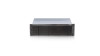
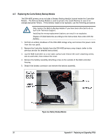
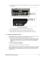
A.4 Replacing the Controller Module in the Primary Array The controller module monitors and manages the logical volumes and the iSCSI network traffic to those volumes. When the controller module is replaced, all of your volume information remains intact because this logical drive information is stored on the hard disk drives. However, your other configuration data (including iSCSI initiator access, network portals and advanced system settings) are stored in the controller module. Although controller module hardware failures are rare, you should save a System Configuration file that can be restored to the new controller, if replacement becomes necessary. Do not replace the controller module based only on LED colors. Only replace the Controller Module when specifically directed to do so by D-Link Technical Support. Before performing this procedure, you must perform an orderly shut-down of the DSN-4X00 primary array, which means that all of your volumes will be unavailable during the replacement procedure. Use the following procedure to replace the controller module on the DSN-4X00 primary array. 1. Perform an orderly shutdown of the DSN-4X00 storage array and remove the power cords from the rear panel. 2. Disconnect all of the network, serial and SAS cables from the controller module. 3. On the controller module, loosen the thumbscrew, swing the ejection lever to the right and pull the Controller Module out of the enclosure (see Figure A-3). Thumbscrew Ejection Lever Figure A-3. Removing the Controller Module on the Primary Array 4. Carefully slide the new controller module into the enclosure. 5. Swing the latch to the left until the controller module is fully-seated in the enclosure (but do not to force the latch if any resistance is encountered), and then secure it with the thumbscrew. 6. Reconnect all network, serial, SAS, and power cables. 7. Switch on the power by turning ON the power supply switches. DSN-4000 Series Hardware Reference Guide 25
-
 1
1 -
2
-
3
-
4
-
5
-
6
-
7
-
8
-
9
-
10
-
11
-
12
-
13
-
14
-
15
-
16
-
17
-
18
-
19
-
20
-
21
-
22
-
23
-
24
-
25
-
26
-
27
-
 28
28 -
 29
29 -
 30
30 -
 31
31 -
 32
32 -
 33
33 -
 34
34 -
 35
35 -
 36
36 -
 37
37 -
 38
38
 |
 |