D-Link DSN-4200 Hardware Reference Guide for DSN-4000 - Page 35
Connecting to the Diagnostic Serial Port
 |
View all D-Link DSN-4200 manuals
Add to My Manuals
Save this manual to your list of manuals |
Page 35 highlights
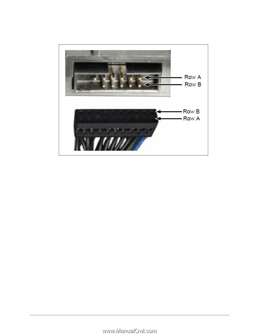
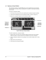
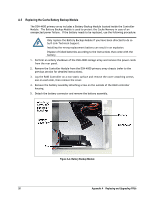
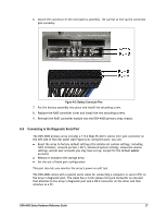
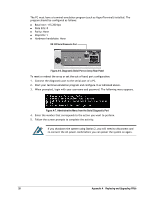
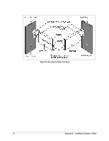
6. Attach the connector of the new battery assembly. Be careful to line-up the connector pins correctly. Figure A-5. Battery Connector Pins 7. Put the battery assembly into place and install the attaching screw. 8. Replace the RAID controller cover and install the two attaching screws. 9. Reinstall the RAID controller module into the DSN-4X00 primary array chassis. A.6 Connecting to the Diagnostic Serial Port The DSN-4X00 primary array includes a 115.2 Kbps RS-232-C stereo mini-jack connector on the left side of the rear panel (see Figure A-6). Using this port, you can: Reset the array to factory default settings (this deletes all custom settings, including iSCSI initiators, network portals, LAG's, advanced system settings, advanced volume settings, and all user accounts you may have set up, except for the default admin account) Reboot or shutdown the storage array Set the out-of-band port configuration This port also lets you monitor the array's power-on self test. The DSN-4X00 comes with a special serial cable for connecting a computer or server (PC) to the array's diagnostic port. The cable has a 3-mm stereo mini-jack connector on one end that attaches to the array's diagnostic port and a DB-9 connector on the other end that attaches to a PC. DSN-4000 Series Hardware Reference Guide 27
-
 1
1 -
2
-
3
-
4
-
5
-
6
-
7
-
8
-
9
-
10
-
11
-
12
-
13
-
14
-
15
-
16
-
17
-
18
-
19
-
20
-
21
-
22
-
23
-
24
-
25
-
26
-
27
-
28
-
29
-
 30
30 -
 31
31 -
 32
32 -
 33
33 -
 34
34 -
 35
35 -
 36
36 -
 37
37 -
 38
38
 |
 |