D-Link DSN-4200 Hardware Reference Guide for DSN-4000 - Page 14
Rear Panel Components
 |
View all D-Link DSN-4200 manuals
Add to My Manuals
Save this manual to your list of manuals |
Page 14 highlights
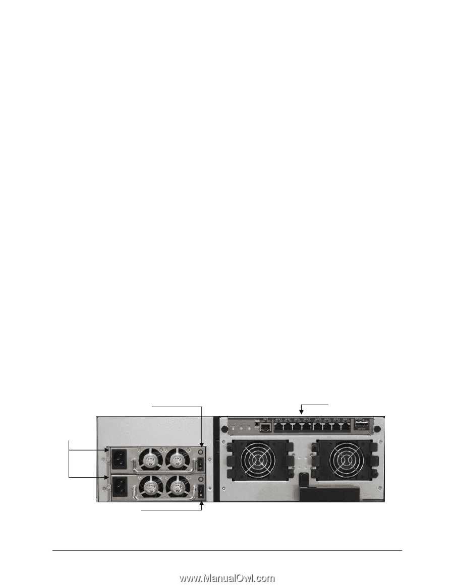
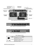
2.2 Rear Panel Components The rear panel of the DSN-4X00 primary array has the following components (see Figure 2-5 through Figure 2-8): Management port (Mgmt) - one 10/100/1000 RJ-45 management is located to the left of the iSCSI data ports. The management port includes port speed and port activity LEDs. For more information, refer to Table 2-3. Four or eight 1-Gigabit RJ-45 iSCSI data ports are located on the rear panel of the DSN4X00 controller module. Each iSCSI data port has port speed and port activity LEDs. For more information, refer to Table 2-4. Diagnostic port (10101/DIAG) - one 115.2 Kbps RS-232-C diagnostic port (3mm stereo mini-jack) is located above the top-right corner of the management port. To connect to this port, use the special RS-232 serial diagnostic cable that was included with your DSN4X00 primary array. Expansion port (SAS EXP) - one SAS expansion port is located to the right of the iSCSI data ports. This connector allows you to attach additional DSN-4000 JBOD expansion arrays to the primary array to increase the system's total storage capacity (see Section 3.9 for more information). RESET button is located above the SAS Expansion port. This button allows you to explicitly restart the system. For more information, refer to Table 2-5. MUTE button is located above the SAS Expansion port. This button allows you to silence the audio alarm when a fault condition has occurred. For more information, refer to Table 2-5. The Controller and Cache Status LEDs are located above the Management Port (see Table 2-6). Battery and Fan Status LEDs are located to the left of the Serial Diagnostic Port, and the SAS Expansion Port Status LED is located above the SAS Expansion Port (see Table 2-6). The rear panel of the DSN-4X00 primary array enclosure has two AC power receptacles and two power switches. For an explanation of the power receptacles and power switches, see Section 3.8. Power Supply Status LEDs (2) Controller Module Redundant AC Power Supplies Power Switches (2) Figure 2-5. Rear View of the DSN-4200 Primary Array 6 Chapter 2 VessRAID 1836i/1846i Series Primary Array Layout
-
 1
1 -
2
-
3
-
4
-
5
-
6
-
7
-
8
-
 9
9 -
 10
10 -
 11
11 -
 12
12 -
 13
13 -
 14
14 -
 15
15 -
 16
16 -
 17
17 -
 18
18 -
 19
19 -
20
-
21
-
22
-
23
-
24
-
25
-
26
-
27
-
28
-
29
-
30
-
31
-
32
-
33
-
34
-
35
-
36
-
37
-
38
 |
 |