D-Link DSN-4200 Hardware Reference Guide for DSN-4000 - Page 16
Table 2-4. 1-Gigabit iSCSI Data Port LEDs, Table 2-5. Rear Panel Buttons and Switches, Table 2-6.
 |
View all D-Link DSN-4200 manuals
Add to My Manuals
Save this manual to your list of manuals |
Page 16 highlights
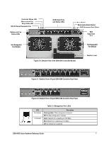
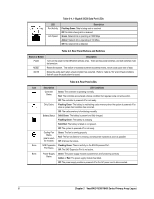
Table 2-4. 1-Gigabit iSCSI Data Port LEDs LED Port Activity Link Speed Description Flashing Green: Data is being sent or received Off: No data is being sent or received Green: Network link is operating at 1000 Mbps Amber: Network link is operating at 100 Mbps Off: No network link is detected Table 2-5. Rear Panel Buttons and Switches Switch or Button Power RESET MUTE Description Turns on the power to the DSN-4X00 primary array. There are two power switches, and both switches must be turned on. Resets the system. This switch is recessed to prevent accidental resets, which could cause loss of data. Mutes the audio alarm when a fault condition has occurred. Refer to Table 2-7 for a list of fault conditions that will cause the audio alarm to sound. Table 2-6. Rear Panel LEDs Icon Description LED Conditions Controller Status Green: The controller is operating normally. Red: The controller encountered a failure condition that requires some corrective action Off: The controller is powered-off or not ready. Dirty Cache Flashing Green: The battery is maintaining cache memory when the system is powered off or when a system fault condition has occurred. Off: The cache memory is functioning normally. Battery Status Solid Green: The battery is present and fully charged. Flashing Green: The battery is charging. Solid Red: The battery is failed or not present. Off: The system is powered-off or not ready. Cooling Fan Status (one for each fan module) Green: The fan is running properly. Red: The fan has failed or is missing, and should be replaced as soon as possible. Off: Unknown fan status. None SAS Expansion Flashing Green: There is activity on the SAS Expansion Port. Port Status Off: The SAS Expansion Port is not active. None Power Supply Green: The power supply module is powered-on and functioning correctly. Status Amber or Red: The power supply module has failed. Off: The power supply module is powered-off or the AC power cord is disconnected. 8 Chapter 2 VessRAID 1836i/1846i Series Primary Array Layout
-
 1
1 -
2
-
3
-
4
-
5
-
6
-
7
-
8
-
9
-
10
-
 11
11 -
 12
12 -
 13
13 -
 14
14 -
 15
15 -
 16
16 -
 17
17 -
 18
18 -
 19
19 -
 20
20 -
 21
21 -
22
-
23
-
24
-
25
-
26
-
27
-
28
-
29
-
30
-
31
-
32
-
33
-
34
-
35
-
36
-
37
-
38
 |
 |
