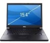
Dell E6500 Service Manual
Dell E6500 - Latitude - Core 2 Duo 2.53 GHz Manual
 |
UPC - 884116029793
View all Dell E6500 manuals
Add to My Manuals
Save this manual to your list of manuals |
Dell E6500 manual content summary:
- Dell E6500 | Service Manual - Page 1
Dell™ Latitude™ E6500 Service Manual Troubleshooting Before Working on Your Computer Base Assembly Hinge Covers Hard Drive WLAN/WiMax Cards WWAN Card WPAN/UWB Cards Flash Cache Modules Fan Processor Thermal-Cooling Assembly Processor Module Memory Coin-Cell Battery Optical Drive LED Cover Keyboard - Dell E6500 | Service Manual - Page 2
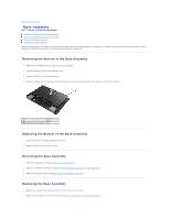
Back to Contents Page Base Assembly Dell™ Latitude™ E6500 Service Manual Removing the Bottom of the Base Assembly Replacing the Bottom of the Base Assembly Removing the Base Assembly Replacing the Base Assembly Before working inside your computer, read the safety information that shipped with your - Dell E6500 | Service Manual - Page 3
Back to Contents Page - Dell E6500 | Service Manual - Page 4
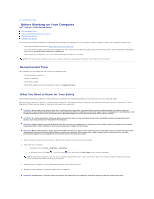
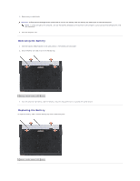
Back to Contents Page Before Working on Your Computer Dell™ Latitude™ E6500 Service Manual Recommended Tools What You Need to Know for Your Safety Removing the Battery Replacing the Battery This document provides procedures for removing and installing the components in your computer. Unless - Dell E6500 | Service Manual - Page 5
5. Remove any installed cards. CAUTION: To help prevent damage to the system board, remove the battery from the battery bay before you service the computer. NOTE: To avoid damage to the computer, use only the battery designed for this particular Dell computer. Do not use batteries designed for other - Dell E6500 | Service Manual - Page 6
Back to Contents Page - Dell E6500 | Service Manual - Page 7
the BIOS Dell™ Latitude™ E6500 Service Manual Flashing the BIOS From a CD/DVD Flashing the BIOS From the Hard Drive If a BIOS-update program CD is provided with a new system board, flash the BIOS from the CD. If you do not have a BIOS-update program CD, download the update from the Dell™ Support - Dell E6500 | Service Manual - Page 8
Back to Contents Page Card Cage Dell™ Latitude™ E6500 Service Manual Removing the Card Cage Replacing the Card Cage Removing the Card Cage Before working inside your computer, read the safety information that shipped with your computer. For additional safety best practices information, see the - Dell E6500 | Service Manual - Page 9
Back to Contents Page - Dell E6500 | Service Manual - Page 10
Back to Contents Page Coin-Cell Battery Dell™ Latitude™ E6500 Service Manual Removing the Coin-Cell Battery Replacing the Coin-Cell Battery Removing the Coin-Cell Battery Before working inside your computer, read the safety information that shipped with your computer. For additional safety best - Dell E6500 | Service Manual - Page 11
Back to Contents Page - Dell E6500 | Service Manual - Page 12
Back to Contents Page Processor Module Dell™ Latitude™ E6500 Service Manual Removing the Processor Module Replacing the Processor Module Removing the Processor Module Before working inside your computer, read the safety information that shipped with your computer. For additional safety best - Dell E6500 | Service Manual - Page 13
the system board. 3. Replace the processor thermal-cooling assembly (see Replacing the Processor Thermal-Cooling Assembly). 4. Replace the fan (see Replacing the Fan). 5. Replace the bottom of the base assembly (see Removing the Bottom of the Base Assembly). 6. Replace the battery (see Replacing the - Dell E6500 | Service Manual - Page 14
Back to Contents Page Processor Thermal-Cooling Assembly Dell™ Latitude™ E6500 Service Manual Removing the Processor Thermal-Cooling Assembly Replacing the Processor Thermal-Cooling Assembly Before working inside your computer, read the safety information that shipped with your computer. For - Dell E6500 | Service Manual - Page 15
-end of assembly 4 captive screws (4) Integrated Graphics Thermal-Cooling Assembly If you have purchased a system board with integrated graphics, follow these steps: 1. Follow the instructions in Before Working on Your Computer. 2. Close the display and turn the computer over. 3. Remove the bottom - Dell E6500 | Service Manual - Page 16
the four captive screws to secure the thermal- cooling assembly to the system board. 3. Replace the fan (see Replacing the Fan). 4. Replace the bottom of the base assembly (see Removing the Bottom of the Base Assembly). 5. Replace the battery (see Replacing the Battery). Back to Contents Page - Dell E6500 | Service Manual - Page 17
Back to Contents Page I/O Daughter Card Dell™ Latitude™ E6500 Service Manual Removing the I/O Daughter Card Replacing the I/O Daughter Card Removing the I/O Daughter Card Before working inside your computer, read the safety information that shipped with your computer. For additional safety best - Dell E6500 | Service Manual - Page 18
5. Replace the palm rest assembly (Replacing the Palm Rest Assembly). 6. Replace the hinge covers (see Replacing the Hinge Covers). 7. Replace the bottom of the base assembly (see Replacing the Bottom of the Base Assembly). Back to Contents Page - Dell E6500 | Service Manual - Page 19
to Contents Page Display Dell™ Latitude™ E6500 Service Manual Removing the Display Assembly Replacing the Display Assembly Removing the Display Bezel Replacing the Display Bezel Removing the Display Panel Replacing the Display Panel Removing the Display Panel Brackets Replacing the Display Panel - Dell E6500 | Service Manual - Page 20
on the system board. 9. Replace the hinge covers (see Replacing the Hinge Covers). 10. Replace the bottom of the base assembly (see Replacing the Bottom of the Base Assembly). 11. Replace the battery (see Replacing the Battery). Removing the Display Bezel Before working inside your computer - Dell E6500 | Service Manual - Page 21
bezel 4 right side of bezel 5 bottom of bezel Replacing the Display Bezel Before working inside your computer, read the safety information that shipped with Regulatory Compliance Homepage at: www.dell.com/regulatory_compliance. 1. Follow the instructions in Before Working on Your Computer. 2. - Dell E6500 | Service Manual - Page 22
cover and lay the display panel flat on your workspace. 2. Pull the pull-tab to disconnect the display cable. Replacing the Display Panel Before working inside your computer, read the safety information that shipped with your computer. For additional safety best practices information, see the - Dell E6500 | Service Manual - Page 23
two M2.5 x 5-mm screws securing the display panel to the display cover. 5. Replace the display bezel (see Replacing the Display Bezel). 6. Replace the display assembly (see Replacing the Display Assembly). Replacing the LED Display Panel 1 display panel 2 display cable 3 display cover 1. Connect the - Dell E6500 | Service Manual - Page 24
brackets are labeled "L" (left) and "R" (right). 1. Replace the display panel brackets. 2. Replace the two M2.5 x 5-m screws (and two each plastic the Regulatory Compliance Homepage at: www.dell.com/regulatory_compliance. 1. Follow the instructions in Before Working on Your Computer. 2. Remove the - Dell E6500 | Service Manual - Page 25
, see the Regulatory Compliance Homepage at: www.dell.com/regulatory_compliance. NOTE: The camera and microphone assembly is optional and may not have shipped with your computer if you did not order them. 1. Follow the instructions in Before Working on Your Computer. 2. Remove the display assembly - Dell E6500 | Service Manual - Page 26
Replacing the Camera and Microphone Assembly Before working inside your computer, read the safety information that shipped with your computer. For additional safety best practices information, see the Regulatory Compliance Homepage at: www.dell.com/regulatory_compliance. 1. Slide the cable connector - Dell E6500 | Service Manual - Page 27
your computer. For additional safety best practices information, see the Regulatory Compliance Homepage at: www.dell.com/regulatory_compliance. 1. Follow the instructions in Before Working on Your Computer. 2. Remove the display assembly (see Removing the Display Assembly). 3. Remove the display - Dell E6500 | Service Manual - Page 28
no unconnected cables on the display cover get caught underneath the panel. 4. Replace the display panel (see Replacing the Display Panel). 5. Replace the display bezel (see Replacing the Display Bezel). 6. Replace the display assembly (see Removing the Display Assembly). Back to Contents Page - Dell E6500 | Service Manual - Page 29
Back to Contents Page Fan Dell™ Latitude™ E6500 Service Manual Removing the Fan Replacing the Fan Removing the Fan Before working inside your computer, read the safety information that shipped with your computer. For additional safety best practices information, see the Regulatory Compliance - Dell E6500 | Service Manual - Page 30
Back to Contents Page Flash Cache Modules Dell™ Latitude™ E6500 Service Manual Removing an FCM Replacing an FCM Before working inside your computer, read the safety information that shipped with your computer. For additional safety best practices information, see the Regulatory Compliance Homepage - Dell E6500 | Service Manual - Page 31
post and hold in position. 3. Replace the screw in the FCM card. 4. Replace the left hinge cover (see Replacing the Hinge Covers). 5. Replace the bottom of the base assembly (see Removing the Bottom of the Base Assembly). 6. Replace the battery (see Replacing the Battery). Back to Contents Page - Dell E6500 | Service Manual - Page 32
Back to Contents Page Hard Drive Dell™ Latitude™ E6500 Service Manual Removing the Hard Drive Replacing the Hard Drive NOTE: Dell does not guarantee compatibility or provide support for hard drives obtained from sources other than Dell. Removing the Hard Drive Before working inside your computer, - Dell E6500 | Service Manual - Page 33
the Base Assembly). 5. Replace and tighten the four M3 x 3-mm hard-drive screws. 6. Replace the battery. 7. Turn the computer over so the top side is up, open the display, and start your computer. 8. If you have installed a new drive, try and boot it. If it doesn't boot: l Use your operating system - Dell E6500 | Service Manual - Page 34
Back to Contents Page Hinge Covers Dell™ Latitude™ E6500 Service Manual Removing the Hinge Covers Replacing the Hinge Covers Removing the Hinge Covers Before working inside your computer, read the safety information that shipped with your computer. For additional safety best practices information, - Dell E6500 | Service Manual - Page 35
Dell™ Latitude™ E6500 Service Manual Removing the Keyboard Replacing the Keyboard Removing the Keyboard Before working the top of the keyboard. CAUTION: The key caps on the keyboard are fragile, easily dislodged, and time-consuming to replace. Exercise care when removing and handling the keyboard - Dell E6500 | Service Manual - Page 36
from the top of the keyboard and carefully snap the panel. 5. Replace the LED cover (see Replacing the LED Cover). 6. Replace the hinge covers (see Replacing the Hinge Covers). 7. Close the display and turn the computer over. 8. Replace the battery (see Replacing the Battery). Back to Contents Page - Dell E6500 | Service Manual - Page 37
Back to Contents Page LED Cover Dell™ Latitude™ E6500 Service Manual Removing the LED Cover Replacing the LED Cover Removing the LED Cover Before working inside your computer, read the safety information that shipped with your computer. For additional safety best practices information, see the - Dell E6500 | Service Manual - Page 38
Back to Contents Page Memory Dell™ Latitude™ E6500 Service Manual Removing a Memory Module Replacing a Memory Module Operation of the Computer Before working inside your computer, read the safety information that shipped with your computer. For additional safety best practices information, see the - Dell E6500 | Service Manual - Page 39
the key in the socket connector. 3. Gently slide the memory module into the DIMM B connector at a 45-degree angle to the system board until it is fully seated. 4. Push the long edge of the memory module down until retaining clips lock the module in place. NOTE: If the memory module is not installed - Dell E6500 | Service Manual - Page 40
is what is expected. 5. To confirm the amount of memory installed in the computer: l In the Microsoft® Windows Vista® operating system, click Start ® Help and Support ® Computer Information. l In the Microsoft Windows® XP operating system, right-click the My Computer icon on your desktop, click - Dell E6500 | Service Manual - Page 41
Page Modem Dell™ Latitude™ E6500 Service Manual Removing the Modem Replacing the Modem Removing the Modem Before working inside your dell.com/regulatory_compliance. 1. Place the modem into the base assembly. 2. Insert the black RJ11 modem cable into the space provided on the base assembly. 3. Replace - Dell E6500 | Service Manual - Page 42
7. Replace the hinge covers (see Replacing the Hinge Covers). 8. Replace the bottom of the base assembly (see Replacing the Bottom of the Base Assembly). Back to Contents Page - Dell E6500 | Service Manual - Page 43
Back to Contents Page Optical Drive Dell™ Latitude™ E6500 Service Manual Removing the Optical Drive Replacing the Optical Drive The optical drive bay supports either an optical drive, a second hard drive, or an air bay for travel. Removing the Optical Drive Before working inside your computer, read - Dell E6500 | Service Manual - Page 44
- Dell E6500 | Service Manual - Page 45
Back to Contents Page Palm Rest Assembly Dell™ Latitude™ E6500 Service Manual Removing the Palm Rest Assembly Replacing the Palm Rest Assembly Removing the Palm Rest Assembly Before working inside your computer, read the safety information that shipped with your computer. For additional safety best - Dell E6500 | Service Manual - Page 46
smart-card cable from the system board. 18. Lift the lever up to disconnect the fingerprint reader cable from the system board (optional). CAUTION: Do switch cable 3 fingerprint reader cable 4 speaker cable 5 touch pad cable Replacing the Palm Rest Assembly Before working inside your computer, - Dell E6500 | Service Manual - Page 47
4. Connect the contactless smart-card cable, the touch pad cable, the speaker cable, the wireless switch cable, and the fingerprint reader cable (optional) to the system board. 5. Replace the four M2.5 x 5-mm screws, two on the silk-screen bar and two on the palm rest. 6. Turn the computer over and - Dell E6500 | Service Manual - Page 48
Back to Contents Page Power Module Dell™ Latitude™ E6500 Service Manual Removing the Power Module Replacing the Power Module Removing the Power Module Before working inside your computer, read the safety information that shipped with your computer. For additional safety best practices information, - Dell E6500 | Service Manual - Page 49
Assembly). 11. Replace the hinge covers (see Replacing the Hinge Covers). 12. Replace the optical drive (see Replacing the Optical Drive). 13. Replace the hard drive (see Replacing the Hard Drive). 14. Replace the bottom of the base assembly (see Replacing the Bottom of the Base Assembly). Back to - Dell E6500 | Service Manual - Page 50
Page Right-Speaker and Fingerprint Reader Cover Dell™ Latitude™ E6500 Service Manual Removing the Right-Speaker and Fingerprint Reader Cover Replacing the Right-Speaker and Fingerprint Reader Cover Removing the Right-Speaker and Fingerprint Reader Cover Before working inside your computer, read - Dell E6500 | Service Manual - Page 51
Fingerprint Reader Cover Before working inside your computer, read the safety information that shipped with your computer. For additional safety best practices information, see the Regulatory Compliance Homepage at: www.dell.com/regulatory_compliance. CAUTION: If you are installing a new fingerprint - Dell E6500 | Service Manual - Page 52
Board Assembly Dell™ Latitude™ E6500 Service Manual Removing the System Board Assembly Replacing the System Board Assembly The system board's BIOS chip contains the Service Tag, which is also visible on a barcode label on the bottom of the computer. The replacement kit for the system board includes - Dell E6500 | Service Manual - Page 53
speaker/fingerprint reader cover (see Replacing the Right- Speaker and Fingerprint Reader Cover). 13. Replace the keyboard (see Replacing the Keyboard). 14. Replace the display assembly (see Replacing the Display Assembly). 15. Replace the optical drive (see Removing the Optical Drive). 16. Replace - Dell E6500 | Service Manual - Page 54
more information). 29. Enter the system setup program to update the BIOS on the new system board with the computer Service Tag. For information about the system setup program, see the Dell™ Technology Guide on your computer or on the Dell Support website at support.dell.com. Back to Contents Page - Dell E6500 | Service Manual - Page 55
Back to Contents Page Dell™ Latitude™ E6500 Service Manual NOTE: A NOTE indicates important information that helps you make better use of your computer. CAUTION: A CAUTION indicates potential damage to hardware or loss of data if instructions are not followed. WARNING: A WARNING indicates potential - Dell E6500 | Service Manual - Page 56
remain on, depending on your BIOS settings. For more information on using the system setup program, see the Dell™ Technology Guide on your computer or on the Dell Support website at support.dell.com. Diagnostic Light Codes During POST To troubleshoot a problem with your computer, read the sequence - Dell E6500 | Service Manual - Page 57
using the system setup program, see the Dell™ Technology Guide on your computer or on the Dell Support website at support.dell.com. The Dell Diagnostics is located on a separate diagnostic utility partition on your hard drive. NOTE: If the computer is connected to a docking device (docked), undock - Dell E6500 | Service Manual - Page 58
that the device you want to test is displayed in system setup and is active. For more information on using the system setup program, see the Dell™ Technology Guide on your computer or on the Dell Support website at support.dell.com. 1. Insert the Drivers and Utilities media into the optical drive - Dell E6500 | Service Manual - Page 59
description exactly as it appears and follow the instructions on the screen. If you cannot resolve the problem, contact Dell Technical Support. NOTE: When contacting Dell Technical Support, have your Service Tag ready. The Service Tag for your computer is located at the top of each test screen - Dell E6500 | Service Manual - Page 60
Operating system not found Contact Dell Technical Support. Solving Problems Follow these tips when troubleshooting your computer: l If you added or removed a part before the problem started, review the installation procedures and ensure that the part is correctly installed. l If a peripheral device - Dell E6500 | Service Manual - Page 61
disc For information about setting power options, see the Dell™ Technology Guide on your computer or on the Dell Support website at support.dell.com. You can also search for the keyword standby in Windows Help and Support for information on power management modes. Hard drive problems Run Check Disk - Dell E6500 | Service Manual - Page 62
Check Now. The User Account Control window may appear. If you are an administrator on the computer, click Continue; otherwise, contact your administrator to continue the desired action. 4. Follow the instructions on the screen. IEEE 1394 Device Problems Before working inside your computer, read the - Dell E6500 | Service Manual - Page 63
at: www.dell.com/regulatory_compliance. The computer does not start up Check the diagnostic lights See Power Problems. Ensure the operating system environments. 1. Click Start ® All Programs ® Accessories ® Program Compatibility Wizard ® Next. 2. Follow the instructions on the screen. Windows Vista - Dell E6500 | Service Manual - Page 64
l Ensure that the program is installed and configured properly. l Verify that the device drivers do not conflict with the program. l If necessary, uninstall and then reinstall the program. Back up your files immediately Use a virus-scanning program to check the hard drive, floppy disks, CDs, or DVDs - Dell E6500 | Service Manual - Page 65
Hardware Troubleshooter See Hardware Troubleshooter. No sound from headphones Check the headphone cable connection Ensure that the headphone cable is securely inserted into the headphone connector. See the Setup and Quick Reference Guide for your computer on the Dell Support website at support.dell - Dell E6500 | Service Manual - Page 66
necessary when installing additional graphics cards; however, the card is required for troubleshooting purposes. If you remove the card, store it in a safe and secure location. For information about your graphics card, go to support.dell.com. Check the diagnostic lights See Diagnostic Lights. Check - Dell E6500 | Service Manual - Page 67
Back to Contents Page WLAN/WiMax Cards Dell™ Latitude™ E6500 Service Manual Removing a WLAN/WiMax Card Replacing a WLAN/WiMax Card Before working inside your computer, read the safety information that shipped with your computer. For additional safety best practices information, see the Regulatory - Dell E6500 | Service Manual - Page 68
the black triangle, and connect the gray antenna cable to the gray triangle. NOTE: Ensure the cables are tucked into the cable channel. 5. Replace the bottom of the base assembly (see Removing the Bottom of the Base Assembly). 6. Replace the battery (see Replacing the Battery). Back to Contents Page - Dell E6500 | Service Manual - Page 69
Back to Contents Page WPAN/UWB Cards Dell™ Latitude™ E6500 Service Manual Removing a WPAN/UWB Card Replacing a WPAN/UWB Card Before working inside your computer, read the safety information that shipped with your computer. For additional safety best practices information, see the Regulatory - Dell E6500 | Service Manual - Page 70
/UWB card. 4. Connect the blue antenna cable to the WPAN/UWB card. 5. Replace the left hinge cover (see Replacing the Hinge Covers). 6. Replace the bottom of the base assembly (see Removing the Bottom of the Base Assembly). 7. Replace the battery (see Replacing the Battery). Back to Contents Page - Dell E6500 | Service Manual - Page 71
WWAN Card Dell™ Latitude™ E6500 Service Manual Removing a WWAN Card Replacing a WWAN Card Before working inside your computer dell.com/regulatory_compliance. Your computer supports a Wireless Wide Area Network (WWAN) card. If you ordered a WWAN card with your computer, the card is already installed - Dell E6500 | Service Manual - Page 72
connectors are keyed to ensure correct insertion. If you feel resistance, check the connectors on the card and on the system board, install WWAN cards in any other Mini-Card slot. 1. Slide the WWAN card into the connector. 2. Press the card down to the alignment post and hold in position. 3. Replace
-
 1
1 -
 2
2 -
 3
3 -
 4
4 -
 5
5 -
 6
6 -
 7
7 -
8
-
9
-
10
-
11
-
12
-
13
-
14
-
15
-
16
-
17
-
18
-
19
-
20
-
21
-
22
-
23
-
24
-
25
-
26
-
27
-
28
-
29
-
30
-
31
-
32
-
33
-
34
-
35
-
36
-
37
-
38
-
39
-
40
-
41
-
42
-
43
-
44
-
45
-
46
-
47
-
48
-
49
-
50
-
51
-
52
-
53
-
54
-
55
-
56
-
57
-
58
-
59
-
60
-
61
-
62
-
63
-
64
-
65
-
66
-
67
-
68
-
69
-
70
-
71
-
72
 |
 |

Dell™ Latitude™ E6500 Service Manual
Troubleshooting
Before Working on Your Computer
Base Assembly
Hinge Covers
Hard Drive
WLAN/WiMax Cards
WWAN Card
WPAN/UWB Cards
Flash Cache Modules
Fan
Processor Thermal
-
Cooling Assembly
Processor Module
Memory
Coin
-
Cell Battery
Optical Drive
LED Cover
Keyboard
Right
-
Speaker and Fingerprint Reader Cover
Palm Rest Assembly
Card Cage
System Board Assembly
I/O Daughter Card
Modem
Power Module
Display
Flashing the BIOS
Notes, Cautions, and Warnings
If you purchased a DELL™ n Series computer, any references in this document to Microsoft
®
Windows
®
operating systems are not applicable.
Information in this document is subject to change without notice.
©
2008-
2009 Dell Inc. All rights reserved.
Reproduction of these materials in any manner whatsoever without the written permission of Dell Inc. is strictly forbidden.
Trademarks used in this text:
Dell
, the
DELL
logo, and
Latitude
are trademarks of Dell Inc.;
Microsoft
,
Windows, Windows Vista, and the Windows Start
button logo are either
trademarks or registered trademarks of Microsoft Corporation in the United States and/or other countries;
Bluetooth
is a registered trademark of Bluetooth SIG Inc.
Other trademarks and trade names may be used in this document to refer to either the entities claiming the marks and names or their products. Dell Inc. disclaims any
proprietary interest in trademarks and trade names other than its own.
Model PP30L
September 2009
Rev. A02
NOTE:
A NOTE indicates important information that helps you make better use of your computer.
CAUTION:
A CAUTION indicates potential damage to hardware or loss of data if instructions are not followed.
WARNING:
A WARNING indicates potential for property damage, personal injury, or death.