Dell E6500 Service Manual - Page 49
Replacing the Power Module
 |
UPC - 884116029793
View all Dell E6500 manuals
Add to My Manuals
Save this manual to your list of manuals |
Page 49 highlights
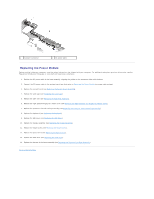
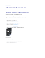
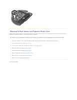
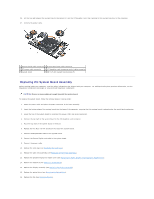
1 DC power connector 2 DC power cable Replacing the Power Module Before working inside your computer, read the safety information that shipped with your computer. For additional safety best practices information, see the Regulatory Compliance Homepage at: www.dell.com/regulatory_compliance. 1. Position the DC power cable in the base assembly, aligning the guides on the connector sides with the base. 2. Connect the DC power cable to the system board (see illustration in Removing the Power Module for proper cable routing). 3. Replace the system board (see Replacing the System Board Assembly). 4. Replace the card cage (see Replacing the Card Cage). 5. Replace the palm rest (see Replacing the Palm Rest Assembly). 6. Replace the right-speaker/fingerprint reader cover (see Replacing the Right-Speaker and Fingerprint Reader Cover). 7. Replace the processor thermal-cooling assembly (see Replacing the Processor Thermal-Cooling Assembly). 8. Replace the keyboard (see Replacing the Keyboard). 9. Replace the LED cover (see Replacing the LED Cover). 10. Replace the display assembly (see Replacing the Display Assembly). 11. Replace the hinge covers (see Replacing the Hinge Covers). 12. Replace the optical drive (see Replacing the Optical Drive). 13. Replace the hard drive (see Replacing the Hard Drive). 14. Replace the bottom of the base assembly (see Replacing the Bottom of the Base Assembly). Back to Contents Page
-
 1
1 -
2
-
3
-
4
-
5
-
6
-
7
-
8
-
9
-
10
-
11
-
12
-
13
-
14
-
15
-
16
-
17
-
18
-
19
-
20
-
21
-
22
-
23
-
24
-
25
-
26
-
27
-
28
-
29
-
30
-
31
-
32
-
33
-
34
-
35
-
36
-
37
-
38
-
39
-
40
-
41
-
42
-
43
-
 44
44 -
 45
45 -
 46
46 -
 47
47 -
 48
48 -
 49
49 -
 50
50 -
 51
51 -
 52
52 -
 53
53 -
 54
54 -
55
-
56
-
57
-
58
-
59
-
60
-
61
-
62
-
63
-
64
-
65
-
66
-
67
-
68
-
69
-
70
-
71
-
72
 |
 |
