Dell Inspiron 1545 Service Manual - Page 48
Replacing the System Board - screen replacement
 |
View all Dell Inspiron 1545 manuals
Add to My Manuals
Save this manual to your list of manuals |
Page 48 highlights
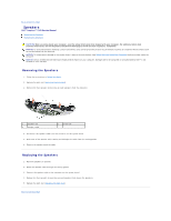
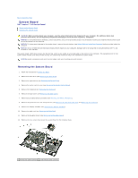
3 speaker cable connector 5 screws (4) 4 system board 13. Disconnect the thermal fan cable, speaker cable, and USB board cable from the respective system board connectors. 14. Lift the system board at an angle toward the side of the computer and out of the computer base. 15. If required, remove any installed Mini-Card (see Removing the Mini-Card). Replacing the System Board 1. If required, replace Mini-Card, (see Replacing the Mini-Card). 2. Replace the system board in the computer base. 3. Connect the thermal fan cable, speaker cable, and USB board cable to the respective system board connectors. 4. Replace the four screws that secure the system board to the computer base. 5. Replace the daughter board (see Replacing the Daughter Board). 6. Replace the palm rest (see Replacing the Palm Rest). 7. Replace the display assembly (see Replacing the Display Assembly). 8. Replace the processor heat sink and the processor (see Replacing the Processor Heat Sink and Installing the Processor). 9. Replace any installed memory modules (see Replacing the Memory Module(s)). 10. Replace the base cover (see Replacing the Base Cover). 11. Replace the keyboard (see Replacing the Keyboard). 12. Replace the center control cover (see Replacing the Center Control Cover). 13. Replace the optical drive (see Replacing the Optical Drive). 14. Replace the hard drive (see Replacing the Hard Drive). 15. Reinstall the ExpressCards in the ExpressCard slot, if any. 16. Slide the battery into the battery bay until it clicks into place. NOTICE: Before turning on the computer, replace all screws and ensure that no stray screws remain inside the computer. Failure to do so may result in damage to the computer. 17. Turn on the computer. NOTE: After you have replaced the system board, enter the computer Service Tag into the BIOS of the replacement system board. 18. Insert the BIOS upgrade CD that accompanied the replacement system board into the appropriate drive. Follow the instructions that appear on the screen. Back to Contents Page
-
 1
1 -
2
-
3
-
4
-
5
-
6
-
7
-
8
-
9
-
10
-
11
-
12
-
13
-
14
-
15
-
16
-
17
-
18
-
19
-
20
-
21
-
22
-
23
-
24
-
25
-
26
-
27
-
28
-
29
-
30
-
31
-
32
-
33
-
34
-
35
-
36
-
37
-
38
-
39
-
40
-
41
-
42
-
 43
43 -
 44
44 -
 45
45 -
 46
46 -
 47
47 -
 48
48 -
 49
49 -
 50
50 -
 51
51
 |
 |
