Dell PowerConnect W-AP175 Dell PowerConnect W-AP175P Installation Guide - Page 8
Identifying Known RF Absorbers/Reflectors/Interferences Sources, RF Absorbers, RF Reflectors
 |
View all Dell PowerConnect W-AP175 manuals
Add to My Manuals
Save this manual to your list of manuals |
Page 8 highlights
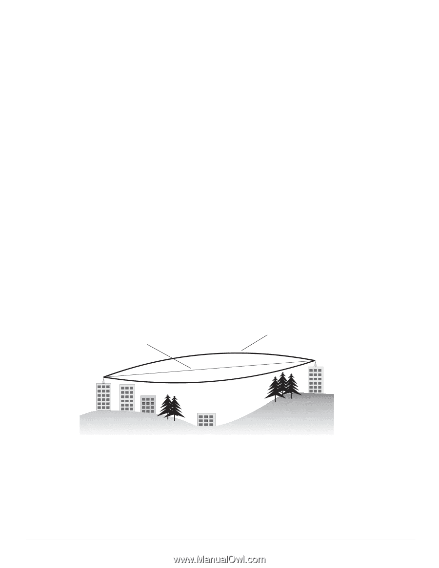
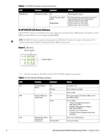
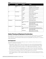
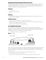
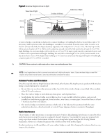
Identifying Known RF Absorbers/Reflectors/Interferences Sources Identifying known RF absorbers/reflectors/interference sources while out in the field during the installation phase is critical. Even though outdoor environments consist of fewer RF absorbers/reflectors/interference sources compared to indoor environments, ensure that these sources are identified and taken into consideration when installing and mounting an AP to its fixed outdoor location. RF Absorbers Cement/Concrete Natural Items: Trees/vegetation Brick RF Reflectors Metal Objects: Roof-installed air-conditioning equipment, chain link fences (depending on aperture size), other wire fences, or water pipes RF Interference Sources Other 802.11a/b/g/n or broadband access equipment operating nearby Industrial RF welding equipment or other Industrial, Scientific and Medical (ISM) equipment that utilizes RF to heat or alter the physical properties of materials Military, Commercial Aviation or Weather Radar Systems Line of Sight (Radio Path Planning) A wireless bridge or mesh link requires a "radio line of sight" between the two antennas for optimum performance. The concept of radio line of sight involves the area along a link through which the bulk of the radio signal power travels. This area is known as the first Fresnel Zone of the radio link. For a radio link, no object (including the ground) must intrude within 60% of the first Fresnel Zone. Figure 4 illustrates the concept of a good radio line of sight. Figure 4 Line of Sight Visual Line of Sight Radio Line of Sight If there are obstacles in the radio path, there may still be a radio link but the quality and strength of the signal will be affected. Calculating the maximum clearance from objects on a path is important as it directly affects the decision on antenna placement and height. It is especially critical for long-distance links, where the radio signal could easily be lost. When planning the radio path for a wireless bridge or mesh link, consider these factors: Avoid any partial line of sight between the antennas Be cautious of trees or other foliage that may be near the path, or may grow and obstruct the path. 8 Dell PowerConnect W-AP175 Outdoor Access Point | Installation Guide
-
 1
1 -
2
-
 3
3 -
 4
4 -
 5
5 -
 6
6 -
 7
7 -
 8
8 -
 9
9 -
 10
10 -
 11
11 -
 12
12 -
 13
13 -
14
-
15
-
16
-
17
-
18
-
19
-
20
-
21
-
22
-
23
-
24
-
25
-
26
-
27
-
28
-
29
-
30
-
31
-
32
 |
 |