Dell PowerEdge T320 Owner's Manual - Page 70
Operating Frequency in MT/s, Maximum DIMM Rank
 |
View all Dell PowerEdge T320 manuals
Add to My Manuals
Save this manual to your list of manuals |
Page 70 highlights
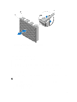
• number of DIMMs populated per channel • DIMM operating voltage • system profile selected (for example, Performance Optimized, Custom, or Dense Configuration Optimized) • maximum supported DIMM frequency of the processor The system contains six memory sockets organized into three channels. In each channel, the release levers of the first socket are marked white and the second socket black. Figure 35. Memory Socket Locations Memory channels are organized as follows: • channel 0: memory sockets A1 and A4 • channel 1: memory sockets A2 and A5 • channel 2: memory sockets A3 and A6 The following table shows the memory populations and operating frequencies for the supported configurations. DIMM Type DIMMs Populated/ Channel UDIMM ECC 1 2 Operating Frequency (in MT/s) 1.5 V 1333, 1066, and 800 1333, 1066, and 800 1.35 V 1333, 1066, and 800 1333, 1066, and 800 Maximum DIMM Rank/ Channel Dual rank Dual rank 70
-
 1
1 -
2
-
3
-
4
-
5
-
6
-
7
-
8
-
9
-
10
-
11
-
12
-
13
-
14
-
15
-
16
-
17
-
18
-
19
-
20
-
21
-
22
-
23
-
24
-
25
-
26
-
27
-
28
-
29
-
30
-
31
-
32
-
33
-
34
-
35
-
36
-
37
-
38
-
39
-
40
-
41
-
42
-
43
-
44
-
45
-
46
-
47
-
48
-
49
-
50
-
51
-
52
-
53
-
54
-
55
-
56
-
57
-
58
-
59
-
60
-
61
-
62
-
63
-
64
-
 65
65 -
 66
66 -
 67
67 -
 68
68 -
 69
69 -
 70
70 -
 71
71 -
 72
72 -
 73
73 -
 74
74 -
 75
75 -
76
-
77
-
78
-
79
-
80
-
81
-
82
-
83
-
84
-
85
-
86
-
87
-
88
-
89
-
90
-
91
-
92
-
93
-
94
-
95
-
96
-
97
-
98
-
99
-
100
-
101
-
102
-
103
-
104
-
105
-
106
-
107
-
108
-
109
-
110
-
111
-
112
-
113
-
114
-
115
-
116
-
117
-
118
-
119
-
120
-
121
-
122
-
123
-
124
-
125
-
126
-
127
-
128
-
129
-
130
-
131
-
132
-
133
-
134
-
135
-
136
-
137
-
138
-
139
-
140
-
141
-
142
-
143
-
144
-
145
-
146
-
147
-
148
-
149
-
150
-
151
-
152
-
153
-
154
-
155
-
156
-
157
-
158
-
159
-
160
-
161
 |
 |
