Dell XPS 630i Service Manual
Dell XPS 630i Manual
 |
View all Dell XPS 630i manuals
Add to My Manuals
Save this manual to your list of manuals |
Dell XPS 630i manual content summary:
- Dell XPS 630i | Service Manual - Page 1
Dell™ XPS™ 630i Service Manual Model DCDR01 www.dell.com | support.dell.com - Dell XPS 630i | Service Manual - Page 2
or loss of data and tells you how to avoid the problem. CAUTION: A CAUTION indicates a potential for property damage, personal Dell Inc. is strictly forbidden. Trademarks used in this text: Dell, the DELL logo, and XPS are trademarks of Dell Inc.; Microsoft, Windows, Windows Vista, and Windows - Dell XPS 630i | Service Manual - Page 3
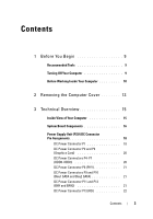
of Your Computer 15 System Board Components 16 Power Supply Unit (PSU) DC Connector Pin Assignments 18 DC Power Connector P1 18 DC Power Connector P2 and P3 (Graphics Card 20 DC Power Connectors P4-P7 (HDD0-HDD3 20 DC Power Connector P8 (PHY 21 DC Power Connectors P9 and P10 (Bay1 SATA and - Dell XPS 630i | Service Manual - Page 4
23 Power Button DC Pin Assignments 23 4 Memory 25 DDR2 Memory Overview 25 Addressing Memory Configurations 27 Installing Memory 27 Removing Memory 29 5 Cards 31 Removing PCI and PCI Express Cards 32 Installing PCI and PCI Express Cards 35 Removing a PCI Express Graphics Card From a Dual - Dell XPS 630i | Service Manual - Page 5
Reader 59 Removing a Media Card Reader 59 Installing a Media Card Reader 60 CD/DVD Drive 63 Removing a CD/DVD Drive 63 Installing a CD/DVD Drive 64 7 Fans 69 Removing the Card Fan 69 Installing the Card Fan 71 Removing the Hard Drive Fan 74 Installing the Hard Drive Fan 76 8 Processor - Dell XPS 630i | Service Manual - Page 6
83 Removing the Processor 83 Installing the Processor 84 10 System Board 87 Removing the System Board 87 Installing the System Board 88 11 Power Supply 91 Removing the Power Supply 91 Installing the Power Supply 92 12 Front I/O Panel 95 Removing the Front I/O Panel 95 Installing - Dell XPS 630i | Service Manual - Page 7
14 Lights 105 Removing the Front LED Board 105 Installing the Front LED Board 106 Removing the Rear LED Board 107 Installing the Rear LED Board 109 15 Replacing the Battery 111 16 Cables 113 Power Cables 113 Power Cables With a Release Latch 113 Power Cables Without a Release Latch 114 IDE - Dell XPS 630i | Service Manual - Page 8
8 Contents - Dell XPS 630i | Service Manual - Page 9
BIOS update program media Turning Off Your Computer NOTICE: To avoid losing data, save and close all open files and exit all open programs before you turn off your computer. 1 Shut down the operating system: a Save and close all open files and exit all open programs. b In the Microsoft® Windows® XP - Dell XPS 630i | Service Manual - Page 10
hold the power button for card. Hold a card by its edges or by its metal mounting bracket. Hold a component such as a processor by its edges, not by its pins. NOTICE: Only a certified service technician should perform repairs on your computer. Damage due to servicing that is not authorized by Dell - Dell XPS 630i | Service Manual - Page 11
all telephone or network cables from the computer. 4 Disconnect your computer and all attached devices from their electrical outlets. 5 Press the power button to ground the system board. NOTICE: Before touching anything inside your computer, ground yourself by touching an unpainted metal surface - Dell XPS 630i | Service Manual - Page 12
12 Before You Begin - Dell XPS 630i | Service Manual - Page 13
the procedures in this section, follow the safety instructions in the Product Information Guide. CAUTION: To guard against electrical shock, NOTICE: Ensure that sufficient space exists to support the system with the cover removed-at least 30 cm (1 ft) of desktop space. 2 Pull back on the cover - Dell XPS 630i | Service Manual - Page 14
2 1 1 computer cover 2 cover release latch 3 With the cover release latch pulled back, grip the sides of the cover, then pivot the top of the cover up and away from the computer. 4 Slide the cover forward and then upward to remove it from the hinge slots. Set it aside in a secure and protected - Dell XPS 630i | Service Manual - Page 15
Technical Overview Inside View of Your Computer 5 1 2 3 4 1 CD/DVD drive bays (2) 3 card fan 5 power supply 2 floppy drive/media card reader 4 hard-drive bays (4) Technical Overview 15 - Dell XPS 630i | Service Manual - Page 16
System Board Components 1 2 34 5 27 26 25 24 23 22 6 7 8 9 10 11 12 13 14 15 16 17 18 19 21 20 16 Technical Overview - Dell XPS 630i | Service Manual - Page 17
) 15 PCI-Express x8 card slot (SLOT3) 16 PCI-Express x1 card slot (SLOT2) NOTE: This slot is not available in the dual-graphics configuration 17 PCI-Express x16 card slot (PRIMARY_GFX_SLOT1) 18 power connector (12V_ATXP) 19 processor (CPU) 20 processor fan connector (FAN_CPU) 21 black memory - Dell XPS 630i | Service Manual - Page 18
Power Supply Unit (PSU) DC Connector Pin Assignments DC Power Connector P1 13 14 15 16 17 18 19 20 21 22 23 24 1 2 3 4 5 6 7 8 9 10 11 12 18 Technical Overview - Dell XPS 630i | Service Manual - Page 19
COM N/C +5 VDC/SE +5 VDC +5 VDC COM 18-AWG Wire Color Orange Orange Black Red Black Red Black Gray Purple Yellow/White Yellow/White Orange Orange Blue Black Green Black Black Black N/A Red Red Red Black Technical Overview 19 - Dell XPS 630i | Service Manual - Page 20
Wire Color White White White Black Black Black NOTE: The P2 and P3 connectors are intended for use with the PCI Express graphics cards whose power requirements exceed 75 watts. DC Power Connectors P4-P7 (HDD0-HDD3) Pin Number 1 2 3 4 5 5 432 1 Signal name +3.3 VDC COM +5 VDC COM +12 VB DC 20 - Dell XPS 630i | Service Manual - Page 21
P8 (PHY) Pin Number 1 2 3 4 1234 Signal name +12 VB DC COM COM +5 VDC 18-AWG Wire Color White Black Black Red DC Power Connectors P9 and P10 (Bay1 SATA and Bay2 SATA) 5 432 1 Pin Number 1 2 3 4 5 Signal name +3.3 VDC COM +5 VDC COM +12 VC DC 18-AWG Wire Color - Dell XPS 630i | Service Manual - Page 22
P13 (FDI) 123 4 Pin Number 1 2 3 4 Signal name +5 VDC COM COM +12 VB DC DC Power Connector P14 (MS BD) Pin Number 1 2 3 4 1234 Signal name +12 VB DC COM COM +5 VDC 22 Technical Overview 18-AWG Wire Color White Black Black - Dell XPS 630i | Service Manual - Page 23
Connectors P15 5678 1 2 34 Pin Number 1 2 3 4 5 6 7 8 Signal name COM COM COM COM +12 VDC +12 VDC +12 VDC +12 VDC Power Button DC Pin Assignments 16-AWG Wire Color Black Black Black Black Yellow Yellow Green/Yellow Green/Yellow Pin Number 1 2 3 4 5 6 7 8 9 10 Signal name +5 VDC PC - Dell XPS 630i | Service Manual - Page 24
24 Technical Overview - Dell XPS 630i | Service Manual - Page 25
on the system board. Your computer supports DDR2 memory. For additional information on the type of memory supported by your computer, see "Specifications" in the Owner's Manual. DDR2 Memory Overview • DDR2 memory modules should be installed in pairs of matched memory size and speed. If the DDR2 - Dell XPS 630i | Service Manual - Page 26
If you remove your original memory modules from the computer during a memory upgrade, keep them separate from any new modules that you may have, even if you purchased the new modules from Dell. If possible, do not pair an original memory module with a new memory module. Otherwise, your computer may - Dell XPS 630i | Service Manual - Page 27
-bit operating system such as Microsoft® Windows® XP, your computer will support a maximum of 4 GB of memory. If you are using a 64-bit operating system, your computer will support a maximum of 8 GB (2-GB DIMMs in each of the four slots) of memory. Installing Memory CAUTION: Before you begin any of - Dell XPS 630i | Service Manual - Page 28
Align the notch on the bottom of the module with the crossbar in the connector. 3 2 1 4 1 cutouts (2) 3 notch 2 memory module 4 crossbar NOTICE: To avoid damage to the memory module, press the module straight down into the connector while you apply equal force to each end of the module. 5 Insert - Dell XPS 630i | Service Manual - Page 29
icon on your Windows desktop and click Properties. 11 Click the General tab. 12 To verify that the memory is installed correctly, check the amount of memory (RAM) listed. Removing Memory CAUTION: Before you begin any of the procedures in this section, follow the safety instructions in the Product - Dell XPS 630i | Service Manual - Page 30
30 Memory - Dell XPS 630i | Service Manual - Page 31
the safety instructions in the Product Information Guide. Your Dell™ computer provides the following slots for PCI and PCI Express cards: • Two PCI Express x16 card slots (can be used in a dual-graphics configuration) • One PCI Express x8 card slot • One PCI Express x1 card slot • Two PCI card slots - Dell XPS 630i | Service Manual - Page 32
1 PCI card 3 PCI Express x16 card slot 5 PCI Express x8 card slot 7 PCI Express x1 card slot 2 PCI Express x16 card 4 PCI Express x8 card 6 PCI Express x1 card Removing PCI and PCI Express Cards NOTICE: To avoid electrostatic discharge and damage to internal components, ground yourself by using a - Dell XPS 630i | Service Manual - Page 33
1 2 3 6 5 4 1 release tab 3 screw 5 fan cage 2 card retainer 4 alignment guide 6 alignment guide release tab 6 Press the securing tab (if present) on the system board connector as you grasp the card by its top corners, and then ease the card out of the connector. Cards 33 - Dell XPS 630i | Service Manual - Page 34
1 2 3 1 PCI Express x16 card 3 PCI Express x16 card slot 2 securing tab 7 Install a filler bracket in the empty card-slot opening. If you are replacing the card, see "Installing PCI and PCI Express Cards" on page 35. NOTICE: Installing filler brackets over empty card-slot openings is necessary to - Dell XPS 630i | Service Manual - Page 35
upgrading to the optional dual-graphics configuration, see "Installing a PCI Express Graphics Card in a Dual Configuration" on page 40 to install a graphics card card is full-length, pull back on the alignment guide release tab to remove the alignment guide from the card fan cage. 6 Position the card - Dell XPS 630i | Service Manual - Page 36
1 2 3 1 PCI Express x16 card 3 PCI Express x16 card slot 2 securing tab NOTICE: Ensure that you release the securing tab to seat the card. If the card is not installed correctly, you may damage the system board. 7 Gently pull the securing tab (if present) and place the card in the connector. - Dell XPS 630i | Service Manual - Page 37
aligned outside the slot 6 alignment guide NOTICE: Do not route card cables over or behind the cards. Cables routed over the cards can prevent the computer cover from closing properly or cause damage to the equipment. NOTICE: An incorrectly attached graphics power cable may result in degraded - Dell XPS 630i | Service Manual - Page 38
turn them on. 13 Install any drivers required for the card as described in the card documentation. NOTE: If you installed a sound card or a network adapter, see "Network Adapter and Sound Card Settings" on page 43. Removing a PCI Express Graphics Card From a Dual Configuration NOTE: Follow the steps - Dell XPS 630i | Service Manual - Page 39
1 2 3 1 graphics card bridge 2 power connectors (2) 3 dual-PCI Express graphics cards 4 Disconnect any cables connected to the card. 5 Remove the PCI Express graphics card (see "Removing PCI and PCI Express Cards" on page 32). NOTICE: Installing filler brackets over empty card-slot openings is - Dell XPS 630i | Service Manual - Page 40
a PCI Express Graphics Card in a Dual Configuration NOTE: To upgrade to or downgrade from a dual-graphics configuration, you will need additional parts that can be ordered from Dell (see "Contacting Dell" in your Owner's Manual). This section pertains to dual PCI Express graphics card configurations - Dell XPS 630i | Service Manual - Page 41
opening. NOTE: If you are upgrading to a dual-graphics card configuration and have a card installed in the PCI Express x1 card slot, remove the card (see "Removing PCI and PCI Express Cards" on page 32). 4 Install the PCI Express graphics card (see "Installing PCI and PCI Express Cards" on page 35 - Dell XPS 630i | Service Manual - Page 42
present 2 on some dual-graphics card configurations) 3 dual-PCI Express graphics cards power connectors (2) NOTICE: To connect a network cable, first plug the cable into the network port or device and then plug the cable into the computer. 9 If present, lower the card-retention device that lies - Dell XPS 630i | Service Manual - Page 43
the setting to Off. If you have removed a sound card: 1 Enter system setup (see "Entering System Setup" in your Owner's Manual), select Integrated Audio Controller, and then change the setting to On. 2 Connect external audio devices to the audio connectors on the back panel of the computer. If you - Dell XPS 630i | Service Manual - Page 44
44 Cards - Dell XPS 630i | Service Manual - Page 45
Drives Your computer supports: • Four SATA devices (hard drives or optical drives) • One IDE device (one hard drive or one optical drive) • One floppy drive or one media card reader NOTICE: When removing and replacing drives, be sure to leave the drive data and power cables connected to the system - Dell XPS 630i | Service Manual - Page 46
About Serial ATA (SATA) Drives Your computer supports up to four serial ATA hard drives and two serial ATA optical drives. SATA drives provide the following benefits setting, the device attached to the last connector on the data cable is the primary device or the boot device, and the 46 Drives - Dell XPS 630i | Service Manual - Page 47
See the drive documentation in your upgrade kit for information on configuring devices section, follow the safety instructions in the Product Information Guide. CAUTION: To guard "Removing the Computer Cover" on page 13). 3 Disconnect the power cable and the data cable from the hard drive. NOTE: If - Dell XPS 630i | Service Manual - Page 48
1 2 3 1 SATA power cable 2 3 SATA data connector (on the system board) SATA data cable 4 Press the black tabs on each side of the hard-drive bracket towards each other and slide the drive up and out of the hard-drive bay. 48 Drives - Dell XPS 630i | Service Manual - Page 49
1 2 3 1 black tabs (2) 3 hard-drive bay 2 hard drive 5 Ensure that all the connectors are properly cabled and firmly seated. 6 Replace the computer cover (see "Replacing the Computer Cover" on page 119). NOTICE: To connect a network cable, first plug the cable into the network port or device - Dell XPS 630i | Service Manual - Page 50
Installing a Hard Drive CAUTION: Before you begin any of the procedures in this section, follow the safety instructions in the Product Information Guide. 1 Follow the procedures in "Before You Begin" on page 9. 2 Remove the computer cover (see "Removing the Computer Cover" on page 13). 3 Remove the - Dell XPS 630i | Service Manual - Page 51
1 2 1 hard drive 2 hard-drive bay NOTICE: Ensure that all the connectors are properly cabled and firmly seated. 7 Connect the power and data cables to the hard drive. NOTE: If you disconnected the data cable while removing the hard drive or if you are installing a new - Dell XPS 630i | Service Manual - Page 52
1 2 3 1 SATA power cable 3 SATA data connector (on the system board) 2 SATA data cable 8 Replace the computer cover (see electrical outlets, and then turn them on. See the documentation that came with the drive for instructions on installing any software required for drive operation. 52 Drives - Dell XPS 630i | Service Manual - Page 53
Drive Panel CAUTION: Before you begin any of the procedures in this section, follow the safety instructions in the Product Information Guide. Removing the Drive Panel 1 Follow the procedures in "Before You Begin" on page 9. 2 Remove the computer cover (see "Removing the Computer Cover" on page 13). - Dell XPS 630i | Service Manual - Page 54
Installing the Drive Panel 1 Follow the procedures in "Before You Begin" on page 9. 2 Remove the computer cover (see "Removing the Computer Cover" on page 13). 3 Align the drive-panel tabs with the side-door hinges. 1 3 2 1 drive-panel tabs (3) 3 drive panel 2 side-door hinges (3) 4 Rotate the - Dell XPS 630i | Service Manual - Page 55
any of the procedures in this section, follow the safety instructions in the Product Information Guide. Removing a Floppy Drive 1 Follow the procedures in "Before 53). 4 Disconnect the power and data cables from the back of the floppy drive. 2 1 1 power cable 2 floppy-drive data cable Drives 55 - Dell XPS 630i | Service Manual - Page 56
5 Slide the drive-release latch towards the base of the computer to release the shoulder screw, and then slide the drive out of the drive bay. 1 2 1 drive-release latch 2 floppy drive 6 Replace the drive panel (see "Installing the Drive Panel" on page 54). 7 Replace the computer cover (see " - Dell XPS 630i | Service Manual - Page 57
3 Remove the drive panel (see "Removing the Drive Panel" on page 53). 4 Remove the existing floppy drive, if applicable (see "Removing a Floppy Drive" on page 55). 5 If no screws are attached to the new floppy drive, check the inside of the drive panel for shoulder screws. If screws are present, - Dell XPS 630i | Service Manual - Page 58
power and data cables to the back of the floppy drive. 8 Check all cable connections and fold cables out of the way to avoid blocking airflow between the fan and cooling documentation that came with the drive for instructions on installing any software required for drive operation. 12 Enter system - Dell XPS 630i | Service Manual - Page 59
CAUTION: Before you begin any of the procedures in this section, follow the safety instructions in the Product Information Guide. Removing a Media Card Reader 1 Follow the procedures in "Before You Begin" on page 9. 2 Remove the computer cover (see "Removing the Computer Cover" on page 13). 3 Remove - Dell XPS 630i | Service Manual - Page 60
or device and then plug it into the computer. 8 Connect your computer and devices to electrical outlets, and then turn them on. Installing a Media Card Reader 1 Follow the procedures in "Before You Begin" on page 9. 2 Remove the computer cover (see "Removing the Computer Cover" on page 13). 60 - Dell XPS 630i | Service Manual - Page 61
the drive panel (see "Removing the Drive Panel" on page 53). 4 Remove the existing media card reader, if applicable (see "Removing a Media Card Reader" on page 59). 5 If no screws are attached to the media card reader, check the inside of the drive panel for shoulder screws. If screws are present - Dell XPS 630i | Service Manual - Page 62
card reader 7 Attach the media card reader cable to the back of the media card reader. 8 Check all cable connections and fold cables out of the way to avoid blocking airflow between the fan and cooling that came with the drive for instructions on installing any software required for drive operation. 12 - Dell XPS 630i | Service Manual - Page 63
instructions in the Product Information Guide. power and data cables from the back of the drive. NOTE: If you are uninstalling the only CD/DVD drive in your computer and will not replace it at this time, disconnect the data cable from the system board and set it aside. 1 2 1 data cable 2 power - Dell XPS 630i | Service Manual - Page 64
5 Slide the drive-release latch towards the base of the computer to release the shoulder screw, and then slide the CD/DVD drive out of the drive bay. 1 3 2 1 drive-release latch 3 CD/DVD drive 2 shoulder screws (3) 6 Replace the drive panel (see "Installing the Drive Panel" on page 54). 7 - Dell XPS 630i | Service Manual - Page 65
3 Remove the drive panel (see "Removing the Drive Panel" on page 53). 4 Remove the existing CD/DVD drive, if applicable (see "Removing a CD/DVD Drive" on page 63). 5 Prepare the CD/DVD drive for installation and check the documentation that accompanied the drive to verify that the drive is - Dell XPS 630i | Service Manual - Page 66
1 2 1 drive-release latch 2 CD/DVD drive 8 Attach the power and data cables to the CD/DVD drive. To locate the system board connector, see "System Board Components" on page 16. 66 Drives - Dell XPS 630i | Service Manual - Page 67
1 2 1 power cable 2 data cable 9 Check all cable connections and fold cables out of the way to avoid blocking airflow between the fan and cooling vents. 10 the documentation that came with the drive for instructions on installing any software required for drive operation. 13 Enter system setup - Dell XPS 630i | Service Manual - Page 68
68 Drives - Dell XPS 630i | Service Manual - Page 69
the Card Fan 1 Follow the procedures in "Before You Begin" on page 9. 2 Remove the computer cover (see "Removing the Computer Cover" on page 13). 3 Gather all the cables from the cable holder on the alignment guide and remove any full-length expansion cards (see "Removing PCI and PCI Express Cards - Dell XPS 630i | Service Manual - Page 70
2 3 1 1 screw 3 tabs (4) 2 card fan cage 6 In succession, carefully pull on each corner of the card fan to detach the rubber grommets securing the card fan to the card fan cage. 70 Fans - Dell XPS 630i | Service Manual - Page 71
1 card fan 3 card fan cage 2 rubber grommet (4) 4 card fan power cable 7 Set the card fan aside in a secure location. Installing the Card Fan NOTICE: Ensure that the fan power cable is correctly routed through the opening in the lower-right corner of the fan cage. 1 With the card fan power cable - Dell XPS 630i | Service Manual - Page 72
1 54 6 1 card fan 3 card fan cage 5 air-flow direction arrow 2 rubber grommet (4) 4 card-fan orientation direction arrow 6 card fan power cable 2 Insert the four tabs along the bottom of the card fan cage into the corresponding slots on the chassis, then slide the card fan cage forward until it - Dell XPS 630i | Service Manual - Page 73
the screw that secures the card fan cage to the chassis. 4 Connect the cables to the master I/O board (see "Power Supply Unit (PSU) DC Connector Pin Assignments" on page 18). 5 Replace any full-length expansion cards that you removed (see "Installing PCI and PCI Express Cards" on page 35). 6 Replace - Dell XPS 630i | Service Manual - Page 74
cover (see "Removing the Computer Cover" on page 13). 3 Remove the card fan cage (see "Removing the Card Fan" on page 69). 4 Disconnect the hard drive fan cable from the FAN_HDD connector on the master I/O board (see "Power Supply Unit (PSU) DC Connector Pin Assignments" on page 18). 5 Slide the - Dell XPS 630i | Service Manual - Page 75
In succession, carefully pull on each corner of the hard drive fan to detach the rubber grommets securing the hard drive fan to the hard drive fan cage. 2 3 1 4 1 hard-drive fan 3 hard-drive fan cage 2 rubber grommets 4 hard-drive fan cable 7 Set the hard drive fan aside in a secure location - Dell XPS 630i | Service Manual - Page 76
cable is correctly routed through the opening in the lower-right corner of the fan cage. 1 With the hard drive fan cable oriented downward, align the rubber grommets in the fan with the openings in each corner of the fan cage, then pull the grommets through until they snap into place. NOTE: Airflow - Dell XPS 630i | Service Manual - Page 77
cable to the FAN_HDD connector on the master I/O board (see "Power Supply Unit (PSU) DC Connector Pin Assignments" on page 18). 4 Replace the card fan cage (see "Installing the Card Fan" on page 71). 5 Replace the computer cover (see "Replacing the Computer Cover" on page 119). NOTICE: To connect - Dell XPS 630i | Service Manual - Page 78
78 Fans - Dell XPS 630i | Service Manual - Page 79
procedure, follow the safety instructions located in the Product Information Guide. Removing the Processor Heatsink 1 Follow the processor heat sink can get very hot during normal operation. Be sure that the heat sink has had sufficient time to cool before you touch it. 3 Disconnect the fan - Dell XPS 630i | Service Manual - Page 80
, lay it upside down or on its side to avoid damaging the heatsink thermal interface. 5 Lift the processor heatsink out of the computer, and set it aside. Installing the Processor Heatsink 1 Follow the procedures in "Before You Begin" on page 9. 2 Remove the computer cover (see "Removing the - Dell XPS 630i | Service Manual - Page 81
4 Tighten the four captive screws. 5 Connect the fan cable to the FAN_CPU connector on the system board (see "System Board Components" on page 16). 6 Close the computer it into the computer. 7 Connect your computer and devices to electrical outlets, and then turn them on. Processor Heatsink 81 - Dell XPS 630i | Service Manual - Page 82
82 Processor Heatsink - Dell XPS 630i | Service Manual - Page 83
instructions in the Product Information Guide. NOTICE: Do not perform the following steps unless you are familiar with hardware removal and replacement. Performing these steps incorrectly could damage your system board. For technical service, see "Contacting Dell" in your Owner's Manual. Removing - Dell XPS 630i | Service Manual - Page 84
: Ground yourself by touching an unpainted metal surface on the back of the computer. NOTICE: You must position the processor correctly in the socket to avoid permanent damage to the processor and the computer when you turn on the computer. NOTE: If the socket release lever is not fully extended - Dell XPS 630i | Service Manual - Page 85
release lever back toward the socket and snap it into place to secure the processor. 5 Replace the processor heatsink (see "Installing the Processor Heatsink" on page 80). 6 Reconnect the power cables to the POWER and 12V_ATXP connectors (see "System Board Components" on page 16) on the system board - Dell XPS 630i | Service Manual - Page 86
7 Replace the computer cover (see "Replacing the Computer Cover" on page 119). NOTICE: To connect a network cable, first plug the cable into the network port or device and then plug it into the computer. 8 Connect your computer and devices to electrical outlets, and then turn them on. 86 Processor - Dell XPS 630i | Service Manual - Page 87
safety instructions in the Product Information Guide Removing the cool before you touch it. 3 Remove the processor heatsink (see "Removing the Processor Heatsink" on page 79). 4 Remove all the expansion cards (see "Removing PCI and PCI Express Cards could lead to computer problems. 6 Disconnect all - Dell XPS 630i | Service Manual - Page 88
boards may be in different locations than corresponding connectors on the existing system board. NOTE: Jumper settings on replacement system boards are preset at the factory. 1 Transfer components from the existing system board to the replacement system board, if applicable. 88 System Board - Dell XPS 630i | Service Manual - Page 89
processor heatsink (see "Installing the Processor Heatsink" on page 80). 5 Replace any expansion cards that you removed (see "Installing PCI and PCI Express Cards system BIOS, as needed. NOTE: For information on flashing the system BIOS, see the Dell Support website at support.dell.com. System Board - Dell XPS 630i | Service Manual - Page 90
90 System Board - Dell XPS 630i | Service Manual - Page 91
CAUTION: Before you begin any of the procedures in this section, follow the safety instructions in the Product Information Guide. Removing the Power Supply 1 Follow the procedures in "Before You Begin" on page 9. 2 Remove the computer cover (see "Removing the Computer Cover" on page 13). NOTICE - Dell XPS 630i | Service Manual - Page 92
the securing tabs on the computer chassis. 10 Slide the power supply towards the expansion cards, to clear the protruding lip of the chassis. 11 Lift the power supply up and out of the computer. Installing the Power Supply 1 Slide the power supply into place, ensuring that the tabs on the rear wall - Dell XPS 630i | Service Manual - Page 93
the system board (see "Installing the System Board" on page 88). 7 Reattach each of the DC power cables that were previously connected, carefully rerouting them as you found them. 8 Replace the computer cover (see computer and devices to electrical outlets, and then turn them on. Power Supply 93 - Dell XPS 630i | Service Manual - Page 94
94 Power Supply - Dell XPS 630i | Service Manual - Page 95
section, follow the safety instructions in the Product Information Guide. 1 Follow the procedures in "Before You Begin" on page 9. 2 Remove the computer cover (see "Removing the Computer Cover" on page 13). 3 Remove any full-length expansion cards (see "Removing PCI and PCI Express Cards" on page 32 - Dell XPS 630i | Service Manual - Page 96
1 3 2 1 FRONT_LED cable 3 front panel 2 tabs (4) 9 Remove the two screws that secure the front I/O panel to the chassis, then slide the front I/O panel towards the chassis frame to remove it completely. 96 Front I/O Panel - Dell XPS 630i | Service Manual - Page 97
front I/O panel Installing the Front I/O Panel CAUTION: Before you begin any of the procedures in this section, follow the safety instructions in the Product Information Guide. 1 Follow the procedures in "Before You Begin" on page 9. 2 Remove the computer cover (see "Removing the Computer Cover" on - Dell XPS 630i | Service Manual - Page 98
the USB_MB cable to the front I/O panel. 8 Replace the card fan cage (see "Installing the Card Fan" on page 71). NOTICE: Ensure that you replace all the " on page 101). 10 Replace any expansion cards that you removed (see "Installing PCI and PCI Express Cards" on page 35). 98 Front I/O Panel - Dell XPS 630i | Service Manual - Page 99
11 Replace the computer cover (see "Replacing the Computer Cover" on page 119). NOTICE: To connect a network cable, first plug the cable into the network port or device and then plug it into your computer. 12 Connect your computer and devices to electrical outlets, and then turn them on. Front I/O - Dell XPS 630i | Service Manual - Page 100
100 Front I/O Panel - Dell XPS 630i | Service Manual - Page 101
Master I/O Board Master I/O Board Components 12 3 11 10 9 45 6 7 8 Master I/O Board 101 - Dell XPS 630i | Service Manual - Page 102
4 media card reader connector (USB_Flexbay) 5 internal USB connector (USB_MB) 6 I/O board power connector (PWR_CONN) 7 card fan connector (FAN_CCAG) 8 rear LED sensor (REAR_LED_SENSOR) 9 hard drive fan connector (FAN_HDD) 10 front I/O panel USB, audio, and lights connector (FRONT_AUDIO_USB_LED - Dell XPS 630i | Service Manual - Page 103
the screw to secure the master I/O board to the metal tray. 3 Reconnect all cables to the master I/O board. 4 Replace the card fan cage (see "Installing the Card Fan" on page 71). 5 Replace the computer cover (see "Replacing the Computer Cover" on page 119). 6 Connect your computer and devices - Dell XPS 630i | Service Manual - Page 104
104 Master I/O Board - Dell XPS 630i | Service Manual - Page 105
Lights CAUTION: Before you begin any of the procedures in this section, follow the safety instructions in the Product Information Guide Removing the Front LED Board NOTE: The front LED board is embedded on the , pivot the front panel away from the computer to release it from the chassis. Lights 105 - Dell XPS 630i | Service Manual - Page 106
panel 2 tabs (4) 6 Disconnect the FRONT_LED cable from the front panel to remove the front panel along with the front panel light board. NOTE: Do not remove the front panel light board embedded on the front panel. Installing the Front LED Board NOTE: The front LED board is embedded on the front - Dell XPS 630i | Service Manual - Page 107
the Rear LED Board 1 Follow the procedures in "Before You Begin" on page 9. 2 Remove the computer cover (see "Removing the Computer Cover" on page 13). Lights 107 - Dell XPS 630i | Service Manual - Page 108
the system cover (see "Replacing the Computer Cover" on page 119). 8 Connect your computer and devices to electrical outlets, and then turn them on. 108 Lights - Dell XPS 630i | Service Manual - Page 109
. 7 Replace the computer cover (see "Replacing the Computer Cover" on page 119). 8 Connect your computer and devices to electrical outlets, and then turn them on. Lights 109 - Dell XPS 630i | Service Manual - Page 110
110 Lights - Dell XPS 630i | Service Manual - Page 111
the procedures in this section, follow the safety instructions in the Product Information Guide. A coin-cell battery maintains computer configuration, date instructions. To replace the battery: 1 Record all the screens in system setup (see "System Setup" in the Owner's Manual) so that you can restore - Dell XPS 630i | Service Manual - Page 112
into the computer. 8 Connect your computer and devices to electrical outlets, and then turn them on. 9 Enter system setup (see "System Setup" in the Owner's Manual) and restore the settings you recorded in step 1. 10 Properly dispose of the old battery. See the Product Information - Dell XPS 630i | Service Manual - Page 113
a Release Latch The following power connectors on your computer have release latches: • Main power cable (see "DC Power Connector P1" on page 18). • Graphics card power cables (see "DC Power Connector P2 and P3 (Graphics Card)" on page 20). • Processor Power cable (see "DC Power Connectors P15" on - Dell XPS 630i | Service Manual - Page 114
the cable up and away from the system board. 1 4 2 3 1 release latch 3 system board power connector 2 tab 4 power connector To connect the power cable to the system board, align the release latch on the power connector with the tab on the system board connector; then push the connector downwards - Dell XPS 630i | Service Manual - Page 115
connector on the system board or drive 4 beveled edge on the power cable To connect a power cable without a release latch, align the beveled edge on the power cable with beveled edge of the power connector on the drive or system board; then press firmly into the connector. IDE and Floppy-Drive - Dell XPS 630i | Service Manual - Page 116
1 2 3 1 IDE ribbon cable 2 cable key 3 IDE connector on the system board/drive SATA Cables NOTE: Using a SATA cable, you can connect only one SATA device to the SATA connector on the system board. To connect a SATA cable, hold the cable by the connector at each end and press firmly into the - Dell XPS 630i | Service Manual - Page 117
1 SATA connector 3 SATA connector hard drive 2 SATA connector on the system board Front I/O Panel Cables NOTE: Most of the front I/O panel, fan, and light cables have similar connectors. The number of pins and the location of the cable key or missing pin may vary. 3 1 2 1 connector on the system - Dell XPS 630i | Service Manual - Page 118
118 Cables - Dell XPS 630i | Service Manual - Page 119
Replacing the Computer Cover CAUTION: Before you begin any of the procedures in this section, follow the safety instructions in the Product Information Guide. CAUTION: Your computer is heavy and can be difficult to maneuver. Seek assistance before attempting to lift, move, or tilt the computer and - Dell XPS 630i | Service Manual - Page 120
1 2 3 1 computer cover 3 hinge slots 2 cover hinge tabs (2) 5 With the help of an assistant, carefully set the computer upright. NOTICE: To connect a network cable, first plug the cable into the network port or device and then plug it into the computer. 6 Connect your computer and devices to
-
 1
1 -
 2
2 -
 3
3 -
 4
4 -
 5
5 -
 6
6 -
 7
7 -
8
-
9
-
10
-
11
-
12
-
13
-
14
-
15
-
16
-
17
-
18
-
19
-
20
-
21
-
22
-
23
-
24
-
25
-
26
-
27
-
28
-
29
-
30
-
31
-
32
-
33
-
34
-
35
-
36
-
37
-
38
-
39
-
40
-
41
-
42
-
43
-
44
-
45
-
46
-
47
-
48
-
49
-
50
-
51
-
52
-
53
-
54
-
55
-
56
-
57
-
58
-
59
-
60
-
61
-
62
-
63
-
64
-
65
-
66
-
67
-
68
-
69
-
70
-
71
-
72
-
73
-
74
-
75
-
76
-
77
-
78
-
79
-
80
-
81
-
82
-
83
-
84
-
85
-
86
-
87
-
88
-
89
-
90
-
91
-
92
-
93
-
94
-
95
-
96
-
97
-
98
-
99
-
100
-
101
-
102
-
103
-
104
-
105
-
106
-
107
-
108
-
109
-
110
-
111
-
112
-
113
-
114
-
115
-
116
-
117
-
118
-
119
-
120
 |
 |

www.dell.com | support.dell.com
Dell™ XPS™ 630i
Service Manual
Model DCDR01